.gif)
Cover Page
MENU
|
Man in Space
A National Historic Landmark Theme Study |

|
|
Rocket Engine Development Facilities |
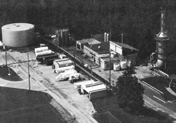
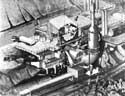
Exterior view of Rocket Engine Test Facility, 1982.
(Courtesy of NASA, NASA/Lewis Research Center Facilities Office)
Rocket Engine Test Facility
| Name: | Rocket Engine Test Facility (Rocket Propulsion Test Facility) |
| Location: | Lewis Research Center, Cleveland, Ohio |
| Owner: | National Aeronautics and Space Administration (NASA) |
| Condition: | Excellent, altered, original location |
| Builder/Architect: | NACA |
| Dates: | 1957-Present |
DESCRIPTION
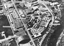
The Rocket Engine Test Facility (RETF) Complex is an integrated stand-alone test facility dedicated to the testing of full scale rocket thrust chambers. The complex is at the south end of the Lewis Research Center (LeRC), Cleveland, Ohio, and occupies approximately ten acres of land. The complex includes two major buildings with extensive support services. The RETF (Building 202) is used for sea level testing of vertically mounted rocket thrust chambers and space simulation testing of horizontally mounted rocket engines. The Rocket Operations Building (ROB) (Building 100) is located one-quarter mile north of RETF and contains the facility remote control room, a shop area, and general office space. This unique test complex has high pressure capabilities, the ability to test with a wide variety of rocket propellants, and space simulation capabilities for large area ratio rocket nozzle tests.
The RETF was completed in the fall of 1957 at a cost of $2-l/2 million to test hydrogen-fluorine and hydrogen-oxygen rocket thrust chambers. The facility test capabilities have been significantly upgraded since it was built.
Facility Systems
The RETF consists of a 1325 square foot test cell containing two test stands, pressurized propellant run tanks and propellant flow line systems, and a rocket exhaust gas treatment combination scrubber and silencing muffler. A 4800 square foot shop service building and 16 large volume high pressure (4000 to 6000 psi) gas storage bottles are adjacent to the test cell. The support systems include permanent on-site bulk storage dewars for cryogenic liquid hydrogen, liquid oxygen, and liquid nitrogen and a large water reservoir; all are connected to the test cell by permanent pipelines. Four small buildings including a pump house, helium compressor shelter, liquid hydrogen pump- vaporizer shelter, and an observation blockhouse are part of the test complex.
Both the high thrust (20,000 lb) vertical test stand and the low thrust (to 1000 lb) horizontal stand exhausts discharge into the common scrubber muffler system for toxicity and sound control. The scrubber system and facility foundations are designed to accommodate rocket engines up to 100,000 lb. thrust while the present engine mounting and plumbing, controls and instrumentation limit testing to a maximum of 20,000 lb. thrust The scrubber system consists of a 100-foot long horizontal tank, 25 feet in diameter containing six water spray banks connected to a vertical stack 20 feet in diameter (which necks down to 6 feet in diameter) by 118 feet high. During a run, water from the reservoir tank flows to the exhaust scrubber at a rate of 50,000 gallons per minute. The hot gases, emerging from the rocket nozzle at velocities of 9000 to 12,000 feet per second and temperatures of about 6000°F, are met with a drenching spray of water and quickly cooled to steam temperature and slowed to a velocity of about 25 feet per second. Additional water sprays condense the steam, and noncondensable exhaust gas emerges from the stack below 160°F and a velocity of about 20 feet per second. Water from the scrubber is ducted to a detention tank for treatment and then discharged to the ground water system.
The 1984 modifications provide a space simulation test capability for the study of extremely large area ratio nozzles (to 1000:1) on small, low thrust rocket engines. The modifications include a large vacuum tank which houses the rocket engine, a long, water cooled diffuser section into which the hot engine exhaust is funneled, an inter-cooler for cooling the exhaust gases, and two gas ejectors to provide the pumping necessary to maintain the low vacuum environment during testing.
Nine individual propellant systems comprised of run dewars and tanks with working pressure ranging from 1500 to 6000 psi are operational and permanently connected to the test stands with stainless steel, vacuum, or liquid nitrogen jacketed pipelines. These systems provide the capability to test the thrust chamber without the need for high pressure rocket turbomachinery and pumps. The separate propellant systems are integrated to support a particular rocket technology program on an as-required basis. Hydraulic, variable position valves control both the pressurant gas flow to the run tanks and the propellant flow to the rocket chambers under tests.
The primary liquid hydrogen, liquid oxygen, cooling water, and hydrocarbon propellant systems are rated at 5000 psi working pressure. Currently, gaseous hydrogen at 4000 psi, gaseous helium at 6000 psi, and gaseous nitrogen at 3000 psi are being stored. A nominal 500,000-gallon water storage reservoir supplies the scrubber and muffler as well as providing a source of water for the 650 gal/min and 1400 gal/min (at 450 psi) pumps and for cooling the rocket altitude simulation system. On-site bulk storage of liquid nitrogen (28,000 gallons) liquid oxygen (2,000 gallons), and liquid hydrogen (18,000 gallons) support the Rocket Engine Test Facility. On-site gas pumping equipment in service at RETF supply gaseous hydrogen at 4000 psi, gaseous helium (automated) at 6000 psi, and gaseous nitrogen (automated) at 3000 psi to the various gas bottle farms.
A flare stack, at the top of the scrubber stack, provides the facility with the capability for open air burnoff of non-regenerative hydrogen, discharged from thrust chambers at rates up to 5 pounds per second.
Control and Instrumentation
The RETF test stands are remotely controlled from the well equipped control room in ROB. Manual, automatic timed, and computer electrical units control the facility instrumentation, data acquisition, hydraulic servo systems, valve operation, and the rocket engine operation from that location. Solid state, programmable flow controllers and sequence timers provide automatic propellant flow control, remote sequence timing, and automatic premissive and cut-off control for the rocket engine under tests. Facility safety monitoring is also provided.
Data are processed through a 200 channel high speed (31K Hz) digitizer multiplexer data acquisition system and fed by a direct digital data link to the Lewis Research Center central data system (IBM 3033 TSS and Cray 1-S computers). This system provides on-line data reduction capabilities to the control room via hardcopy terminals and CRTs located at ROB. Analog data systems provide "quick look" test data through four oscillograph recorders. System pressures are displayed on panel meters in the control room for facility remote control. Closed circuit television systems and a sound monitoring system provide real time data necessary for the remote control of rocket tests. A facility intercommunication system, and emergency communication system, and two independent telephone systems all provide the communications network necessary for safe rocket test operations. [1]
STATEMENT OF SIGNIFICANCE
The Rocket Engine Test Facility (RETF) is nationally significant because of its contribution in the development of the lighweight, regeneratively cooled hydrogen engine. The RETF was built in 1956 by the National Advisory Committee for Aeronautics (NACA) at the Lewis Research Center for the purpose of sea level testing of vertically-mounted rocket engines. The construction and use of the RETF was the next logical step in the continuing mission of the Lewis Research Center in the field of aircraft propulsion systems.
The Lewis Research Center was from the beginning of its history a propulsion center for the National Advisory Committee for Aeronautics. It was from this early work which bridged the transition from reciprocating engines to newer gas turbine jet engines that Lewis made its early mark for NACA. In the years immediately before the creation of NASA in 1958 technical personnel at Lewis begin to experiment with the possibilities of using hydrogen as a rocket fuel. Hydrogen was a desirable fuel because of its low weight and high specific impulse. It was a powerful fuel that appeared to hold promise in the development of high performance rocket engines. Hydrogen was also a dangerous fuel to handle due to the possibility of explosion and the need to use exotic oxidizers such as flourine and oxygen.
By the late 1950s researchers at Lewis became convinced that the desirability of using hydrogen-oxygen as a fuel for upper stage rockets was not only desirable but practicable. This data on the use of liquid hydrogen-oxygen combination developed at Lewis in the RETF was rapidly put to use by NASA contractors in developing liquid hydrogen rockets for the American Space Program.
The specific accomplishments that resulted from this work at the RETF were the development of the RL-10 engine for the Centaur rocket, the J-2 engine for the Saturn rocket, and hydrogen-oxygen engines currently used by the Space Shuttle. The development of the technology needed to handle liquid hydrogen-oxygen cannot be overestimated. The use of the Centaur and Saturn rockets have made possible the American exploration of space in both the manned Apollo program and the unmanned program to explore the planets and the solar environment. The technology used to build the Centaur, Saturn, and current Space Shuttle rockets can be directly attributed to the work of the Lewis Research Center in the RETF in its effort to support the continuing propulsion needs of NASA for its many space programs and missions.
The RETF is an active NASA facility that is now engaged in research to improve rocket technology programs in support of the Advance Space Shuttle, Orbit Transfer Vehicles, and the newly announced Space Station Project.
FOOTNOTES
1. Wayne Thomas, "Description of the Rocket Engine Test Facility" (Unpublished Report, Lewis Research Center, 1984), pp. 1-4.
BIBLIOGRAPHY
Bilstein, Roger E. Stages to Saturn. Washington, D.C.: National Aeronautics and Space Administration, 1980.
Sloop, John L. Liquid Hydrogen as a Propulsion Fuel, 1945-1959. Washington, D.C.: National Aeronautics and Space Administration, 1978.
Technical Facilities Catalog Vol. I. Washington, D.C.: National Aeronautics and Space Administrative, 1974.
Thomas, Wayne. "Description of the Rocket Engine Test Facility." Unpublished Report, Lewis Research Center, 1984.
PHOTOGRAPHS
(click on the above photographs for a more detailed view)
 Top
Top
Last Modified: Mon, Jan 8 2001 10:00:00 am PDT
http://www.cr.nps.gov/history/online_books/butowsky4/space5.htm
![]()