.gif)
Cover Page
MENU
|
Man in Space
A National Historic Landmark Theme Study |

|
|
Apollo Hardware Test Facilities |
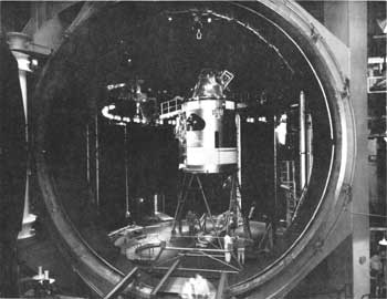
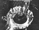
Interior View of Chamber A with Apollo Spacecraft, 1968.
(Courtesy of NASA, NASA/Houston Public Affairs Office)
Space Environmental Simulation Laboratory
| Name: | Space Environmental Simulation Laboratory (SESL) |
| Location: | Lyndon B. Johnson Space Center, Houston, Texas |
| Owner: | National Aeronautics and Space Administration (NASA) |
| Condition: | Excellent, unaltered, original site |
| Builder/Architect: | NASA |
| Dates: | 1965-Present |
DESCRIPTION
The Space Environment Simulation Laboratory (SESL) is in building 32 at the Lyndon B. Johnson Space Center (JSC) in Houston, Texas. The SESL contains two large man-rated chambers, instrumentation and data systems, and support facilities.
Chamber A is the largest of the JSC thermal-vacuum test facilities. Its usable test volume and high-fidelity space simulation capabilities are adaptable to thermal-vacuum tests of a wide variety of test articles.
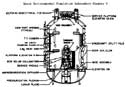
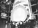
The major structural elements of the chamber are the rotatable floor, the 40 foot diameter access door, and the dual manlocks at the floor level and at the 31 foot level.
The chamber floor, which is 45 feet in diameter, can be rotated by manual control ± 1800 about its vertical axis at continuously variable angular velocities up to a maximum of 0.8 rpm.
Test articles are normally inserted into the chamber by means of overhead cranes and a dolly and track structure that extends from the high-bay area into the chamber. Two 100,000 lb. cranes are used outside the chamber and four independently operated 50,000 lb. cranes, lowered through removable sections of the top head, are employed inside the chamber.
The dual manlocks provide a means for the test crew to move from ambient air pressure to the thermal-vacuum environment and back. They also provide for the maintenance of rescue crewmen at convenient intermediate pressures during manned test operations. When the inner door is bolted, either of the manlocks can be used as an altitude chamber for independent tests.
In Chamber A, a test article can be irradiated from either the top or the side with high-fidelity solar simulation. The solar simulation modules can be arranged in various dimensional configurations to meet most requirements. This chamber can also generate thermal plasmas simulating those found in low Earth orbit.
Chamber B, the smaller man-rated chamber, has the same basic capability as Chamber A and can accommodate a variety of smaller scale tests more economically and with faster response. Major structural elements of the chamber are the removable top head, the fixed chamber floor, and a dual manlock at the floor level.
The load-bearing floor area is 20 feet in diameter and will support a concentric load of 75,000 lb.
Two rolling bridge cranes with a capacity of 100 000 lb. are used to remove the chamber top and to insert large test articles.
The dual manlock provides easy access to the test articles as well as a means of transporting test crewmen to the test environment and back during manned tests. The manlock can also be used as an altitude chamber for independent tests. In addition, one manlock is equipped with a water deluge system and other features that permit its use for manned operations with oxygen-rich residual atmospheres.
A solar simulation array, mounted on the top head, is modular in design to facilitate changes in location and beam size to accommodate test requirements.
The solar simulation modules are on-axis with xenon lamp sources. The source and collection optics are outside the chamber, with the collimating optics inside the chamber. Solar incident angles other than vertical can be achieved by installing mirrors in the chamber to redirect the solar beam. [1]
Only Chambers A and B are within the boundary of the National Historic Landmark.
STATEMENT OF SIGNIFICANCE
The Space Environment Simulation Laboratory (SESL) has a significant association with the manned spacecraft program of the United States. The SESL was designed, built, and used to conduct thermal-vacuum testing for all United States manned spacecraft of the Apollo-era. The large size of both chambers in the SESL meant that full scale flight hardware could be tested for a variety of design and development problems involving such factors as operating temperatures, fluid leak rates, changes in absorptive or emissive properties of thermal coatings and other materials. This testing was absolutely essential to man rate flight hardware. The safety of the astronauts and the success of the manned space program depended on information that resulted from these tests in the SESL.
Since it was constructed in 1965, the SESL has tested all Apollo command and service modules, Apollo lunar modules, spacesuits for extra-vehicular activity, the Skylab/Apollo telescope mount system, various Space Shuttle systems, the Apollo/Soyuz docking module, and various large scale scientific satellite systems such as the parabolic reflector subsystem of the Applications Technology Satellite. The thermal vacuum testing done at the SESL since 1965 has been a significant factor contributing to the success of both the manned and unmanned space program of the United States.
FOOTNOTES
Thermal Vacuum Laboratories User Guide (Houston, Texas: Lyndon B. Johnson Space Center, 1981), pp. 4-5.
BIBLIOGRAPHY
Brooks, Courtney G., Grimwood, James M., and Swenson, Loyd S. Chariots for Apollo: A History of Manned Lunar Spacecraft. Washington, D.C.: National Aeronautics and Space Administration, 1979.
Brooks, Courtney G., Ertel, Ivan D., and Newkirk, Roland W. The Apollo Spacecraft: A Chronology Vol. IV. Washington, D.C.: National Aeronautics and Space Administration, 1978.
Major Test Facilities of the Engineering and Development Directorate. Houston, Texas: Manned Spacecraft Center, 1966.
Technical Facilities Catalog Vol. II. Washington, D.C.: National Aeronautics and Space Administration, 1974.
Thermal Vacuum Laboratories User Guide. Houston, Texas: Lyndon B. Johnson Space Center, 1981.
Technical Facilities Catalog Vol. III. Washington, D.C.: National Aeronautics and Space Administration, 1974.
PHOTOGRAPHS

(click on the above photographs for a more detailed view)
 Top
Top
Last Modified: Mon, Jan 8 2001 10:00:00 am PDT
http://www.cr.nps.gov/history/online_books/butowsky4/space18.htm
![]()