An official website of the United States government
Here's how you know
Official websites use .gov A
.gov website belongs to an official government
organization in the United States.
Secure .gov websites use HTTPS A
lock (
) or https:// means you've safely connected to
the .gov website. Share sensitive information only on official,
secure websites.
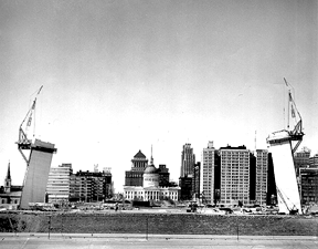
There are nine images in this animation that show the Arch at different points during its construction, between February 29, 1964 - October 28, 1965.
The architecture of the Arch is one of its most interesting aspects. In a radical departure from traditional buildings, it does not have an internal structure or skeleton. Instead, the steel skin supports its own weight – no bones about it!
How Was it Made?
The first step was digging the foundations. The foundations are made of reinforced concrete and extend 60 feet deep, with 30 feet embedded in bedrock. This provides substantial structural strength to the Arch. Structural engineers Severud, Elstad, Krueger, and Associates reported that even in strong winds of 55 pounds per square foot (equivalent to a 150 mph wind), the top of the Arch would only deflect 18 inches east to west. The legs of the Arch are aligned on a north-south axis.
To prepare the site, MacDonald Construction Company, the general contractor for the project, excavated 300,000 cubic feet of earth and rock. Each leg of the Arch is secured to its foundation with 252 alloy-steel tensioning bars, or tendons, which extend 34 feet below the top of the foundations. At ground level, only the outer corners of each triangular base were pre-stressed using groups of 63 steel bars.
To streamline the construction process, Stress Steel Corp., the fabricators, pre-assembled the 35-foot-long steel bars into groups of 21 for efficient shipping and installation. Each group has three rows of seven bars, with the middle row starting 10 feet above the bottom. The bars, made of alloy steel with a diameter of 1-3/4 inches, have an ultimate strength of 145,000 psi. The steel bars, grout tubes, anchors, and bracing all needed to be fabricated and assembled at the shop, which required the use of specially designed jigs.
The ends of the bars were threaded into 1-3/4-inch-thick steel end plates. Rigid steel tubes, 1-1/2 inches in diameter, were tack welded to these end plates, serving as grout tubes around the steel bars and acting as stiffeners for the 21-bar assemblies during shipping and concrete pouring. Steel angle braces were also included for added rigidity during handling, along with steel cross-plates for extra support.
Each completed bar assembly weighed less than 3 tons, allowing for quick and easy handling. Six assemblies, containing a total of 126 bars, filled a truckload for delivery to the job site.
Pre-Stressing the Foundation
Each group of tensioning bars required precise positioning to fit both the curvature of the Arch and the tapering cross-section of its legs. Once the steelwork was in place, concrete was poured in layers of about 5 feet each. Post-tensioning of the bars began after the 5,000-psi concrete reached a strength of 4,000 psi, which typically took 7 to 10 days. A hydraulic jack applied a load of 71 tons to each bar, totaling 18,000 tons for each leg. The engineers specified a strict sequence for tensioning the bars.
The full load was applied to each bar in one operation with a 100-ton capacity center-hole hydraulic jack that worked against a 1-3/4 inch thick steel jacking plate embedded in the top of the concrete. Each 1-1/4 inch diameter bar was surrounded by welded steel tubing with an inside diameter of 1-1/2 inches, creating minimal space between the bar and the tubing's inner wall. This meant relatively high pressures were needed during the grouting process. To simplify this operation, pairs of grout tubes on adjacent tensioning bars were connected at their lower ends by specially designed steel grout pipes that were 1 inch in diameter. Grouting was completed using a high-pressure worm-type pump that forced the grout down one tube and up the adjacent one. This technique utilized the hydraulic pressure in the first tube to fill the second, eliminating the need for additional grout pipes and bleed openings. The top of the second tube acted as a bleed opening to expel any trapped air.
When the steel construction on the south leg reached about 120 feet, it became apparent that the bars weren’t elongating properly during post-tensioning due to jamming in the grout tubes. To address this, post-tensioning tendons were coupled every 12 feet along the station line, with each coupler surrounded by a "coupler shield"—essentially a wider piece of tubing. If concrete seeped into the shield, it would fill the space above the coupler. Ultimately, an additional 12 tendons were added from that elevation up to the 300-foot mark, where the concreting was completed.
Extra steel was incorporated into the upper sections of the Arch. When the keystone sections were placed, hydraulic jacks applied a crown thrust to increase the compressive bending stress in the upper parts of the Arch's legs, countering the tensile stress from wind loads. Following the tendon issues, an extra 10 percent of crown thrust was applied to further enhance the compressive strength and compensate for the pre-stress loss caused by the jammed tendons.
The additional steel in the upper region of the Arch helps resist added axial and bending stresses from the increased crown thrust. In addition to the vertical pre-stressing of the concrete foundation, horizontal post-tensioning was used for the part of the foundation slab designed as a cover above the access tunnel to the Arch. Forty-two 1-1/4 inch diameter bars within flexible steel grout tubes were also pre-stressed in the same manner as the vertical bars.
Above the foundation, the concrete in the walls of the Arch was pre-stressed up to a height of 300 feet. Above this level, the space between the inner and outer walls is hollow, with steel bracing connecting the two skins. This design reduces sway by concentrating most of the weight in the concrete-filled lower sections of the Arch. The massive foundations and solid walls are characteristic of a weighted catenary arch, which is structurally the strongest type of arch, as the thrust passes through the legs and is absorbed in the foundations. In contrast, other arch shapes can experience pressure that forces the legs apart.
Fabricating the Steel
If you were to look at a cross-section of each leg of the Arch, you’d see that it's shaped like a triangle with two walls and a hollow space in the middle. At the base, that hollow space in the middle is 40 feet wide, and it gets narrower (15 1/2 feet) at the top. The inside wall is made of a strong A-7 carbon steel that is 3/8 inches thick, but at the corners, it's even thicker (1.75 inches) to make it stronger. The outside wall is made of polished stainless steel, using 900 tons of it in thin panels that are 1/4 inch thick. These panels come in different sizes, from large ones that are 6 x 18 feet to smaller ones that are 6 x 5 1/2 feet. The steel is type/grade 304, with a #3 finish type. The walls were made in sections and then bolted together at the Pittsburgh and Warren, Pennsylvania factories of the Pittsburgh-Des Moines Steel Company (PDM).
PDM built two huge machines to help with welding. One machine was used for joining the inner carbon steel pieces, and the other, which was bigger, was used for the stainless steel. To put the stainless steel panels together, they used a special type of welding called MIG welding, which uses a mix of Metal Inert Gasses to protect the welds from heat. They checked the welds with X-rays to make sure everything was done right. After welding, they cleaned the stainless steel to remove any marks left from the heat.
After the stainless-steel plates for the sections up to the 300-foot level were welded together, they were turned over and moved to a worktable where they were cut to size. Operators using templates welded rows of 5/16-inches stainless-steel studs to these plates. Then Z-bars were fastened to the studs with carbon-steel nuts tightened to 22-1/2 feet -lbs. with a torque wrench.
For the Arch sections up to the 300-foot level, high-strength steel bolts were attached to the Z-bars. These bolts passed through holes in the inner skin of carbon steel and were held in place by nuts that applied a squeezing force to the concrete core of the wall "sandwich," creating a friction bond. To resist local bending, the outer and inner skins act as the top and bottom flanges of a beam, providing a stressed-skin action comparable to that employed in modern aircraft design.
Above the 300-foot mark, all the Arch’s weight is supported by the outer stainless steel skin and the inner carbon steel skin. Vertical steel pieces called diaphragms connect these two skins and help stop the inner layer from buckling. There are also steel angles placed between the diaphragms to strengthen the outer layer.
Spot welding was chosen for attaching the carbon-steel stiffeners to the stainless-steel skin to eliminate the warping that would be caused by heat if arc welding were used. Except for a few seconds of localized heat, spot welding is practically heatless.
Once the Arch sections were completed, they were transported to St. Louis on special train cars called gondola cars. Two "sandwich" wall sections rode side by side, their stainless sides facing each other but held apart by steel uprights covered with wood and neoprene. Steel rods welded to the carbon-steel plates and to the steel sides of the cars secured each section.
Assembling The Arch
At the job site, cranes equipped with a tubular steel spreader-bar placed the sandwich panels upright in a specially constructed storage area. Initially, the sides of the triangular sections were prefabricated at the plant and sent to the site as three legs of a triangle. Assembling these sections at the site required extremely rigid controls for positioning and welding the corners, but any additional pre-assembly in the shop was impossible because the resulting sections would have been too large for shipment. Triangular sections for higher positions in the Arch had smaller dimensions and could be fabricated and shipped as three dog-leg-shaped pieces, each with a short side and a long side. This way, the corners could be welded in the shop, leaving the simpler task of welding along the sides for the field workers.
At the site, the triangular wall sections were put together on a 56 x 125 foot concrete welding pad. To protect the welding work, this pad was covered with a steel-framed shelter measuring 56 x 60 feet and standing 20 feet high, topped with corrugated galvanized steel. Canvas tarpaulins that could be raised and lowered provided extra protection at the ends. The entire shelter was mobile, riding on wheels so it could be moved over the pad as sections of the Arch were assembled.
Once a section was completed, a crane lifted it from the welding pad onto a specially designed railroad car that had a 42 x 52 foot deck made of 24 WF beams. This car featured an outrigger on rubber-tired wheels to support one corner of the triangular Arch section. A tractor pushed the railroad car along special tracks to bring it next to the Arch leg.
Specially designed creeper cranes then climbed the Arch legs to lift the completed section about 4 inches above the previously placed section and set it down on three 35-ton screw jacks. These jacks accurately positioned the section, leaving a small gap for welding. The first section on each leg was anchored to the foundation using bolts that were either 5/8 inches or 1 inch in diameter and tightened manually.
To ensure stability during transportation and concreting, the corners of the triangular section were reinforced with adjustable steel pipe struts that were 5 inches in diameter and with 12 WF steel-beam wales.The inner plates of carbon steel were welded with low hydrogen electrodes using a normal welding procedure. Semiautomatic gas-shielded welding was used to join the outside stainless-steel surfaces. After welding, concrete was placed in the walls and post-tensioned. Concreting was stopped at the 300-foot level; above this point the triangular sections were fabricated with diaphragms between their outer and inner skins.
Welding the sections together caused some deformation due to heat shrinkage from the welds. Later, when these sections were attached to the legs, they had to be forced into position, which caused slight buckling of the stainless-steel surface. After reviewing the welding process, the steel erector decided to slightly curve (or camber) the walls of each triangular section by about 1-1/2 inches over 35 feet. This way, after the welding shrinkage, the walls would still line up straight.
Interior installations, including prefabricated steel stairs, tracks for the passenger-train conveyor system, utility pipes, and electrical wiring, were added to each Arch leg from both the bottom entrance and the top, depending on the stage of construction.
Workmen's Elevator
A unique temporary elevator system was created to transport workers up and down during the construction of the Arch. Designed by Marshall Elevator Co., this system included some innovative features: it had a travel path that could be extended as the Arch grew taller, used interference-free radio control inside the elevator car (eliminating the need for collector rails or hanging electrical cables), and included a mechanism to keep the cab level at all times.
Each leg of the Arch had a creeper derrick track that served as a guide for the elevator car. Two hoist cables were attached to the top of the car and ran straight up one track beam to the base of the creeper derrick. From there, the cables crossed a 24-foot span to the other track beam and then went down to the base and horizontally to separate drums on a hoist at ground level.
The elevator was made up of a main structural steel frame or sling, onto which a sub-frame was welded to support the tiltable cab. This main frame was held in place and guided along the flange of the track beam by two sets of six steel rollers located at the top and bottom of the frame. A specially designed tilt-sensing mechanism, along with a motor-operated leveling device, ensured the cab remained level.
Creeper Derricks
Both legs of the Arch acted as freestanding cantilevers before completion and were erected simultaneously without scaffolding. For the first few triangular sections, up to a height of 72 feet, crawler cranes were used to lift the sections from the ground. Above that height, two large creeper derricks, each weighing 100 tons, were employed to raise 12-foot-high sections that weighed 50 tons each.
These derricks could pull themselves up the curved legs of the Arch. They had adjustable supports that kept them level, regardless of the height and curve of the legs. Since it was impractical for workers to climb up and down to reach their work areas, the platforms of the derricks (measuring 43 x 32 feet) were accessed by a passenger elevator. These platforms were also equipped with a tool shed for the workers, as well as sanitary facilities and communications equipment.
Two vertical tracks supported the sled that held the derrick and platform. These tracks, made from 12 WF steel beams with cover plates on both sides, were spaced 24 feet apart and positioned about 2 feet away from the outer curve (extrados) of the Arch legs. Each track was securely attached using brackets and held in place with four high-strength steel bolts, each 1-1/4 inches in diameter.
The sled was connected to the tracks by four high-strength steel pins that were 5-3/4 inches in diameter. Telescoping steel legs extended between the outer corners of the platform and the lower part of the sled, with pin connections at both ends. As construction progressed and the curvature of the Arch increased, the telescoping legs were shortened to keep the derrick platform level. Sections of track, each about 48 feet long, were added as needed, allowing the entire derrick to move upward after it placed four sections of the Arch. Lifting an Arch section into place took only about a half hour.
The stabilizing truss in place on the Gateway Arch.
Stabilizing Truss
The initial design for the Arch included the use of guy cables at about the 530-foot mark to provide stability. However, calculations showed that this would require either one 6-inch cable or two 3-inch cables for each leg. This would be quite expensive, especially since the cables couldn’t be reused effectively. Due to this cost and some additional issues related to the cables, the designers decided to use a stabilizing strut or truss instead at the 530-foot level.
When the Arch reached that height, the two creeper derricks worked together to lift and position a steel stabilizing truss that was 255 feet long. This truss connected the tops of the two legs and braced them against each other while additional sections were added to complete the Arch. The truss was similar to a bridge, fabricated in the shop using small wide-flange beams and tubular sections made from high-strength construction alloy steel. It was assembled on-site using 325 high-strength bolts and lifted into place as a single unit.
The truss measured 40 feet wide and 15 feet deep, weighing approximately 60 tons. It was connected to the Arch with a steel harness that fit around each leg, ensuring that the extra weight and wind forces would be transferred directly to the foundations. At each end of the truss, two 45-ton horizontal jacks were used at the points where the strut met the harness, applying pressure to secure the brace onto the legs.
After installing the stabilizing truss, 21 additional sections were added to each leg of the Arch. The next step was to place the final section to complete the structure. A jacking frame was used to apply pressure against the two legs, allowing this last section to be set into position. Once the Arch was complete, the stabilizing strut was lowered by the creeper derricks, which then began their descent down the legs, dismantling and lowering their tracks along the way. They also plugged and smoothed out the bolt holes in the stainless steel surface during this process.