|
By Christopher Edwards, Park Ranger This article is focused on the direct drive steam turbine engines of the coastal liners SS Yale, SS Harvard, SS Northern Pacific, and the SS Great Northern. Most histories that cover the marine steam turbine go into very little detail about how original direct drive type actually worked. This article is a scholarly attempt to fill this gap, and was written for those interested in the finer points of historic steam technology. 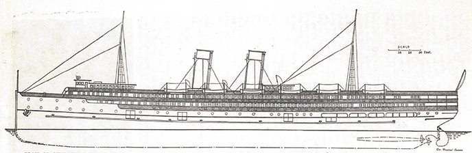
Image Source: The Nautical Gazette, “New American Turbine Steamers Yale and Harvard,” The Nautical Gazette 71, no. 23 (December 29, 1906): 388. (SS=Steam Ship) 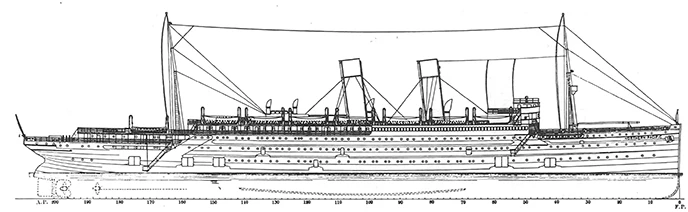
Image Source: International Marine Engineering, “S.S. Great Northern and Northern Pacific,” International Marine Engineering 19, no.12 (December, 1914): 538. One of the most fascinating subjects of Pacific Coast maritime history is that of coastal liner service. This was a chapter of west coast maritime enterprise that contained elements of grandeur, excitement, romance, and especially outright technological power. Competition too was an ever constant companion to coastal steamship lines. In particular, it was competition with, and within, the railroads that led to the ultimate effort of coastal liners on western shores, the deployment of direct drive steam turbine driven coastal liners. In particular the turbine-driven SS Yale, SS Harvard, SS Northern Pacific, and SS Great Northern (later known as the SS H.F. Alexander). Liners such as these tend to only be recognized via the passenger experience. However, the fame that these vessels gained in their day was due, chiefly, to the power of their engines and their ability to drive them at high speeds of between 21 to 23 knots.[1] This was far in excess of their reciprocating engined contemporaries and predecessors. There was, however, a price to be paid. For though the technology of steam turbines was state of the art in the first two decades of the 20th century, engines of this direct drive type were only economic when run at high speed.[2] It was this state of the art, yet imperfect, maritime technology that brought coastal travel on the west coast to its zenith. Despite this and the fact that some extremely famous liners such as the Lusitania, Mauritania and Aquitania also used this direct drive technology, many maritime technology histories barely describe how this worked. It is this gap that we will address here. 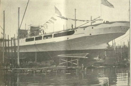
Photo Source: The Nautical Gazette, “New American Turbine Steamers Yale and Harvard,” The Nautical Gazette 71, no. 23 (December 29, 1906): 387. Although the steam turbine took many years of development before its practical use in marine engineering, most historians give Charles Parsons credit for introducing the steam turbine to world of marine propulsion. This he did in sensational fashion during a British Naval Fleet Review in 1897 celebrating the Queen's jubilee. During the review, Parsons, on his turbine driven yacht Turbinia, raced back and forth through the fleet while pursuing British warships, equipped with traditional reciprocating engines, proved unable to catch him. With this display of nautical speed, naval and merchant marine industry took note and began a more earnest look into steam turbine application. There are two primary categories of turbine, radial (where steam flows from or to the turbine's center) and axial (where steam flows parallel to the axis of the turbine rotor.)[3] For marine propulsion, the axial flow turbine proved more suited and it is this type we will consider here. Additionally, there are two main ways to apply steam power to a turbine. These are the impulse and reaction principles.[4] In an impulse turbine the incoming steam is first expanded in a nozzle. In allowing steam to expand in this way the pressure of the steam decreases, but its speed increases. As a result, when the steam contacts the blades of the turbine, it does so with a considerable impact or impulse.[5] It is primarily the force of this impulse on the blades that causes the turbine to rotate. 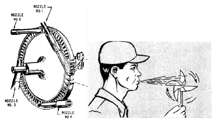
Image source: United States Navy, Fireman: NAVEDTRA 10520-H. (Washington, DC: United States Government Printing Office
On the other hand, the reaction principle does not utilize traditional nozzles. Instead, the steam enters the turbine more directly and flows through the turbine's blades. As these blades are curved, each time the steam hits a blade it reverses its direction of flow. Due to the law of physics which states "Every action has an equal and opposite reaction…" as the steam hits a blade and reverses its direction there is a force imposed on the blade in the opposite direction, though there is still a slight impulse effect as well. Within the turbine, the blades are alternately mounted on rotating and fixed structures. In this way, the fixed blades served to redirect the steam so that the moving blades all have force imparted to them in the same direction. This results in rotation of the turbine as the steam expands through it.[6]
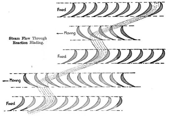
Image source: G.J. Meyers, Steam Turbines: A Treatise Covering U.S. Naval Practice(Annapolis, MD: United States Naval Institute, 1917), 65.
It was this reaction principle that Parsons used on the Turbinia and which became the preferred type of marine turbine in its early days of application. As a result, Parsons's reaction turbines were what equipped the first United States turbine equipped merchant vessels. One final caveat about the turbine is that, unlike reciprocating engines, they are not directly reversible. So, for moving a ship astern, separate reversing turbines, of reduced power, were provided for maneuvering in confined waters, such as when near a dock. The sister ships Yale and Harvard were only the third and fourth US merchant vessels to be equipped with steam turbines. (They were only preceded by the SS Creole and SS Governor Cobb.)[7] The Yale and Harvard had been built in 1907 to provide overnight service between New York City and Boston. Though effective in this role, financial and industrial politics resulted in them being sold and transferred for service on the West Coast.[8] Through two different service periods before and after World War I, these two ships made a grand reputation for themselves on the over night service between San Francisco and Los Angeles (with a later additional leg to San Diego). Providing this kind of service was only possible due to the speed that their turbine engines could deliver.
Likewise, the sister ships Northern Pacific and Great Northern were also built for over night service. These vessels were launched in 1914 and owned by James J. Hill, owner of both the Northern Pacific and Great Northern railroads (hence the names of his two coastal liners). Their route connected Seattle to San Francisco. By running this route with a fast overnight service, Hill hoped to compete with his rival Ned Harriman who owned the Union Pacific and Southern Pacific railroads. Harriman had the rail route right connecting the Pacific Northwest down to San Francisco and would not allow passengers on Hill's railroad to connect for through service to San Francisco. Hence Hill's decision to build fast ships to circumvent Harriman by a sea route.[9] Thus, these two pairs of sister ships both ended up with the very specific requirement for as high a speed as technology of the day could provide. As indicated above, however, these two groups of sister ships not only served different sections of the west coast, but were also of very different size and were built about seven years apart. Therefore, there were some differences in their propulsion systems. The most notable difference was in their boiler installation. The older Yale and Harvard, at 386.5 feet long, 50.5 feet molded beam (63 feet over the guards above the waterline) and 3,731 gross tons, were equipped with industry standard scotch fire tube boilers which provided steam at 155 pounds per square inch.[10] The newer Northern Pacific and Great Northern, at 524 feet long, 63 foot beam, and 8,255 tons gross, were given more modern water tube boilers that produced steam at 220 pounds per square inch.[11] With this difference in size and steam conditions, the turbine engines were also of different sizes and powers. The turbines of the smaller Yale and Harvard produced 10,000 shaft horse power for 20-21 knots[12] while the larger turbines of the Northern Pacific and Great Northern delivered 25,000 shaft horse power for about 23 knots.[13] Despite these differences, however, the two engine designs had more in common than not. As stated above, the turbines which equipped these west coast coastal liners were of a type described as direct-drive reaction turbines. The nature of the reaction principle has already been described, but direct drive is something many current readers may be unfamiliar with. Most students of steam history know that as a technology, steam turbines are most efficient when rotating at high speeds. For marine applications this is a problem since, on board a ship, the main goal is to rotate one or more propellers to create thrust to move the ship through the water. Counter to the high speed needs of the turbine, propellers are most efficient at lower speeds as they tend to cavitate (the quick forming and collapsing of bubbles) at high speeds.[14] This decreased efficiency. Hence the eventual development of turbo-electric and geared turbine systems. In both of these systems, the turbine could run at its efficient higher speeds while the propeller ran at its lower speeds. Both of these techniques, however, took time to develop. So during the turbine's initial years of marine use, direct drive, wherein the turbine was directly connected to the propeller shaft with no rotational reduction in between, was the only option. Herein lies the imperfection of these west coast vessels. In order to make this, as yet, unperfected, technology economically usable at all, two things had to be done. The first was to make the propellers smaller while the turbines were made as large as possible. This would permit the turbine, with its larger diameter to rotate somewhat slower than it would if built small, while the smaller propeller rotated somewhat faster without loosing too much of its efficiency. The second thing was to expand the steam over multiple turbines of differing sizes. In this way, much like multiple expansion reciprocating engines, a turbine installation would involve utilizing multiple turbines, each of which which used steam at differing pressures. This would permit expanding steam as much as possible without needing a turbine of gigantic proportions. However, unlike its reciprocating steam engine contemporary, these multiple turbines all required their own propeller shaft.[15] So in essence, upon entering one of these early turbine driven vessels, what a visitor would see was a single engine system using multiple turbines turning multiple shafts (three shafts in the case of the west coast coastal liners.) Thus the engine installation could expand the steam in the turbines to very low, sub-atmospheric, pressure levels and achieve some amount of efficiency. Even so, the efficiency achievable was only enough to make a ship intended for high speed operation economic. Hence during the early days of marine turbines using direct-drive, only express passenger carrying ships, not the more common general cargo ships, tended to use this technology. Due to this imperfection, the west coast overnight vessels, were used as they were. 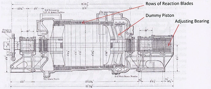
Image Source: International Marine Engineering, “SS Great Northern and Northern Pacific,” International Marine Engineering 19, no.12 (December, 1914): 543. 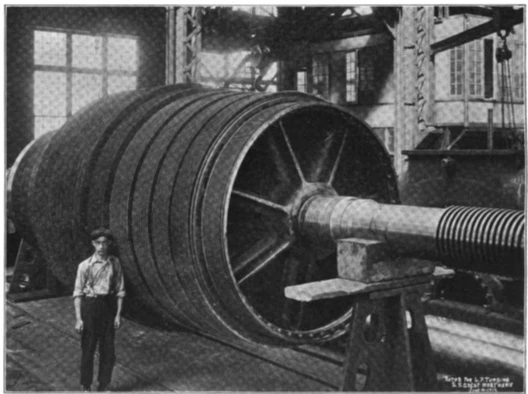
Photo Source: International Marine Engineering, “SS Great Northern and Northern Pacific,” International Marine Engineering 19, no.12 (December, 1914): 541. 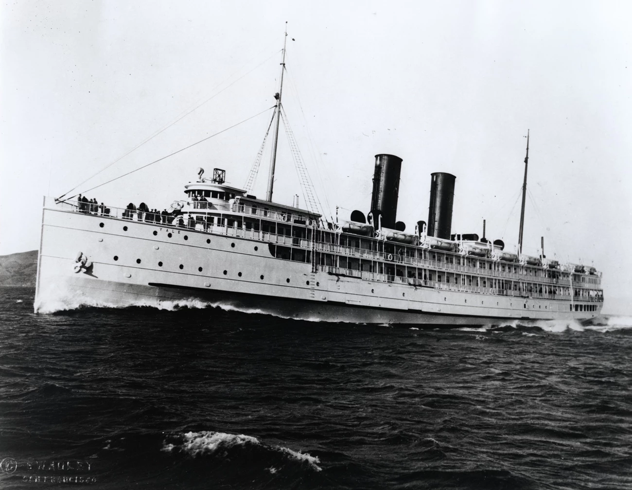
Photo Source: P03-14.8pl, Swadley photographer, San Francisco Maritime National Historical Park. 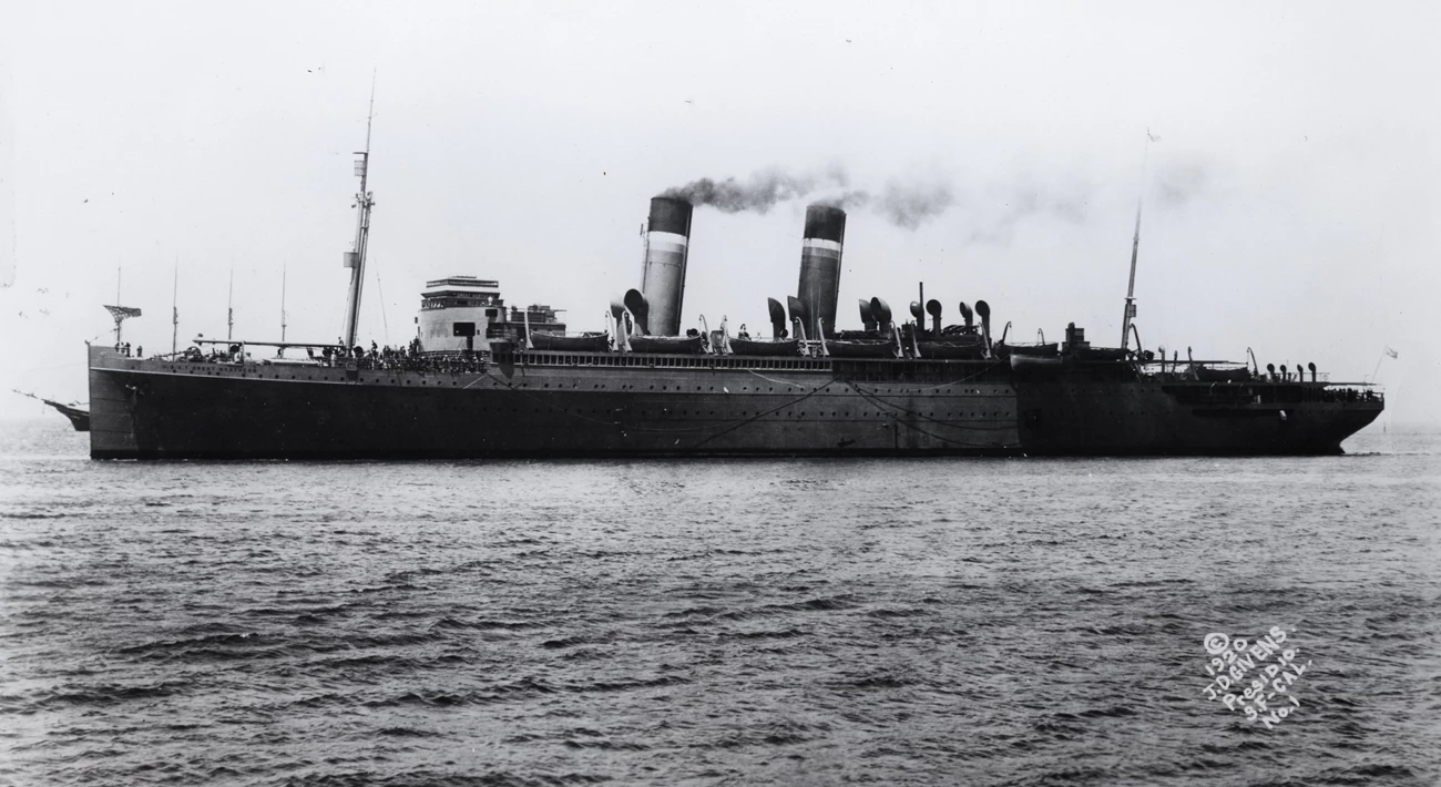
Photo Source: B07.7,943pl, Corbaley Collection, San Francisco Maritime National Historical Park.
So with this technological background established and its imperfection understood, let us take a look in the engine room of the coastal liners of the west coast and consider the main advantage, power, that this type of engine could provide west coast travelers. Despite the differing powers and dimensions of the SS Yale/Harvard and the SS Northern Pacific/Great Northern turbine installations, their overall design and layout were very similar. So we shall consider them together.
An informed traveler heading north or south off the West Coast, would have understood that having a fast ship to beat the railroad schedule was a challenge in part because of the geography of the coast itself. Unlike the East Coast, the western coastline was of convex shape. So any passenger ship in competition with a railroad, upon departure, would first have to head not just north or south as it were, but also west.[16] Otherwise a captain would risk shipwreck on what is known to be a very unforgiving coast. Nothing but a fast ship could handle this requirement without falling behind the railroad schedule. For a steam powered reciprocating engine to attempt the speed necessary for this geography handicap, it meant an uncomfortable ride for passengers due to the vibrations such an engine produced at high speed. Also, from the reciprocating engineer's point of view, high speed was undesirable as well due to the increased malfunctions high speed cause on reciprocating engines. Additionally, any major engine malfunction could result in shipwreck on the coast. Fortunately, steam turbines were not only capable of the high speed necessary for competing with the railroads, but due to its ability of being able to convert the energy in steam directly into rotary motion, it also inherently ran without the vibrations associated with reciprocating engines. So a visitor to a turbine equipped engine room, even before stepping through the engine room door, would have noticed from the moment the ship cleared the harbor that the ship, though picking up speed for its run along the coast, was relatively vibration free.[17] The only noticeable motions would be those associated with the ocean itself.
Upon entering the engine room proper, a visitor would notice the limited head room the engine needs. The turbines, within their casings/cylinders were laid flat along the engine room floor. Some head room above them was needed for maintenance requirements but not because of the dimensions of the turbines themselves and nothing near the headroom required by a vertical inverted reciprocating engine.[18] With the ship underway, perhaps even near full speed, a noticeable absence of noise would have stood out. There would be a certain high-pitched whining sound, but even this would not be as loud as later turbines would make due to their gears. An engine room visitor would see mainly stillness. Except for the rotating propeller shafts extending aft, the turbines themselves presented no visible moving parts. A visitor making their way along the deck gratings would realize how much space along the lower levels of the engine room the turbines actually take up for there are three of them. On the coastal liners of the West Coast, the arrangement included a high pressure turbine on the center line along with two low pressure turbines, one to port and one to starboard.
Though it is simple in principle, the piping and numerous pieces of auxiliary machinery would, to the gaze of a visitor, appear highly complex. There was main steam line piping leading, first, to the high pressure turbine, then exhausting from the opposite end of this high pressure turbine, two lines branched out to feed the high pressure exhaust into the low pressure turbines on either side. Then from the exhaust ends of the low pressure turbines there were exhaust lines that led to the condensers that turned the exhaust steam back into water which was fed back to the boilers. For maneuvering and reversing, the high pressure turbine was by-passed and steam was sent directly to the low pressure and astern turbines which were contained in the same casings as the ahead low pressure units.
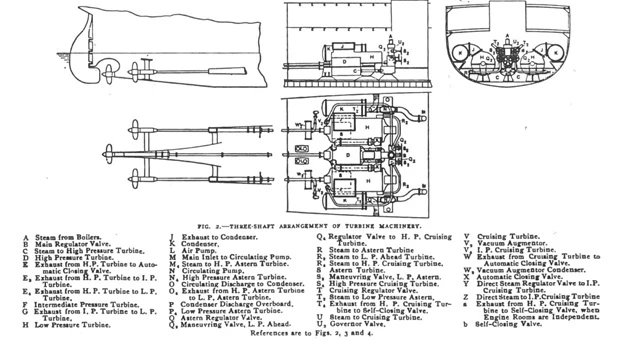
Photo Credit: International Marine Engineering Vol 11 (December, 1906) p. 478. 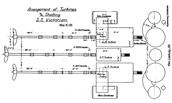
Image Source: Commander A.B. Canaga, U.S.N., “The Turbine Steamship Victorian,” American Society of Naval Engineers 17, no. 2, (May, 1905): 411. 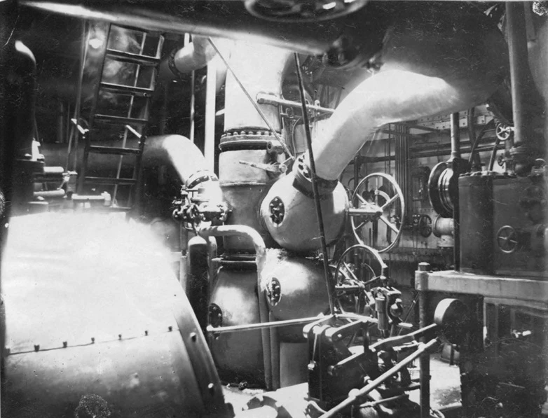
Photo Source: Howard C. Fisher and Philip E. Young, Thesis, Service Test on Steamship Harvard (Parsons Turbine) Power and Speed (Cambridge, MA: Massachusetts Institute of Technology, May 1909). 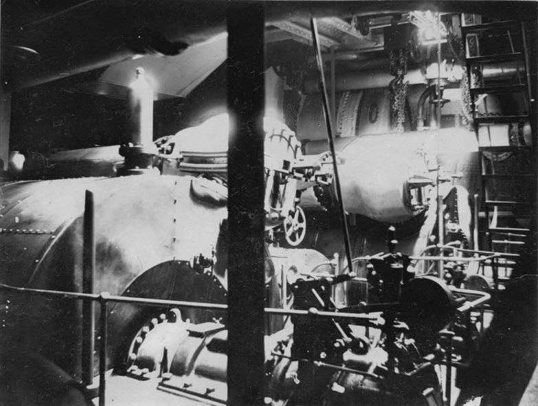
Photo source: Howard C. Fisher and Philip E. Young, Thesis, Service Test on Steamship Harvard (Parsons Turbine) Power and Speed (Cambridge, MA: Massachusetts Institute of Technology, May 1909). Other smaller steam pipe lines supplied power to the auxiliary machinery. The purposes of all this machinery varied. Some were dynamos for producing electricity, others were pumps (for feed water to the boilers, bilge pumps etc.) and still others were the air pumps (and vacuum augmenters/air ejectors) which were just as vital to these coastal liners as the turbines themselves. These air pumps were important because part of what made the turbines practical is that they could make use of steam pressure below atmospheric pressure. This is something that reciprocating engines could not do. But this was only possible if you had air pumps removing air from the condensers and producing a partial vacuum.[19] For express liners using direct drive turbines, such as these west coast vessels did, one of the surprising, interesting, and trickiest things to understand was how the thrust produced by the propellers was transmitted to the ship. Most marine engines utilize a thrust bearing to transmit this energy into the ship and to prevent it from going into the engine itself. In the case of these direct drive-turbines, that is not exactly how the thrust was handled. Though there was a thrust bearing (though some sources also call it an adjusting bearing)[20] the thrust was primarily transmitted through the engine and its casing directly. This arrangement is very counter intuitive to students of marine propulsion technology. In most cases, such an arrangement would risk heavy damage to the engine. In this case, though, instead of deranging the engine and its parts, most (and some sources say all) of the thrust produced by the propellers was counteracted by the thrust created by the steam within the turbine itself.[21] Steam flow was arranged so that it entered the turbine at its forward end and flowed axially to its aft end. This powerful flow of steam created thrust within the turbine itself which was counteracted by the thrust coming in the opposite direction from the propeller. Additionally, since steam thrust within the turbine was usually not enough to fully counteract propeller thrust, the turbine designers allowed for steam entering the turbine to press onto a flat surface of the forward end of the turbine drum. In allowing steam to act upon this surface, this produced additional longitudinal force that aided the thrust produced by the axial flow of the steam through the turbine to fully counteract the thrust coming the opposite way from the propeller.[22] The only time when this system would not properly balance would be when the turbine was being started, stopped, or sped up or down. For these situations, there was a traditional-looking thrust bearing locate at the very forward end of the turbine. Once the turbine was running and fully sped up, the thrust would balance out and little to none would be imparted on the bearing.[23] So, by this point in the explanation, it can be seen how the thrust is balanced within the turbine. However, this force still needed to be transmitted into the ship. With the thrust balanced, the normal way to transfer this energy into the ship's structure would be to simply bolt the turbine casing rigidly to the ship. One problem the designers had to deal with though, was that the turbine and its casing heated and expanded asymmetrically. This was due to steam entering the casing at the forward end and flowing axially to its aft end. As the steam did this, it cooled down. This meant that the heat imparted to the surrounding casing was not equal from one end of the turbine to the other. The result was that the forward end of the turbine heated and expanded more than the aft end did. The solution settled upon was to mount the turbine so that the forward end could actually slide forward as it heated and expanded. The aft end was rigidly bolted to the ship's structure and performed the function of thrust-block seat.[24] With this engineering arrangement, from start to finish, thrust transmission occurred as follows. Thrust produced by the propeller moved axially forward via the propeller shaft where it entered the rotor of the turbine. Within the turbine, this thrust was counteracted by a combination of steam thrust flowing aft axially through the rotor and thrust imparted onto the forward end of the rotor drum. Thus balanced within the turbine, the thrust now transfers from the shaft/rotor/steam combination, into the casing of the turbine. With the need to provide for the expansion of the forward end of the turbine, the thrust cannot transfer into the ship at the turbine's forward end. So this thrust travels back aft down the length of the turbine casing to its aft end where the turbine is rigidly attached to the ship and here transfers into the ship's structure and pushes the ship through the water. As designed, built, and installed on the Yale, Harvard, Great Northern, and Northern Pacific, this direct drive turbine technology represented state of the art marine propulsion technology in the first two decades of the 20th century. It solved the problem of providing high speed at sea with little vibration and significantly reduced occurrence of break downs and maintenance. On the West Coast, this allowed travelers the luxury of an overnight passage between major ports/cities and increased sea transport's ability to compete with the railroads. Within this nascent technology however, there were several imperfect aspects, such as thrust transfer and economy of operation. The methods and solutions invented to deal with these problems though, were fascinating. Some, such as thrust transfer appear to have been entirely successful. Others, such as economy of operation proved more chronic. Until the development of turbo electric systems and gear cutting technology for producing effective reduction geared turbines for ship propulsion, direct drive would remain uneconomic for most commercial shipping roles. The one exception was express passenger service. It was in this market that a fast running turbine attached to a fast rotating propeller could pay for itself and return a profit to its owners. Even in this service niche, though, it usually took a full, or near-full, passenger load to produce that profit. And when combined with continuing railroad competition, growing auto truck and bus competition, very bad labor relations, and the onset of the caustic economic environment of the Great Depression, direct drive turbines could not remain economically viable. In fact, given these circumstances, just about all coastal passenger service on the west coast died out in the 1930s. That said, these west coast direct drive turbine coastal passenger ships represented the height, and nadir, of west coast passenger ship propulsion technology. And though this technology had very definite imperfections, it is, perhaps, these very imperfections that make the engines of these ships so very fascinating. 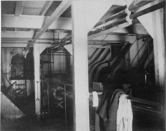
Photo Source: Howard C. Fisher and Philip E. Young, Thesis, Service Test on Steamship Harvard (Parsons Turbine) Power and Speed (Cambridge, MA: Massachusetts Institute of Technology, May 1909). 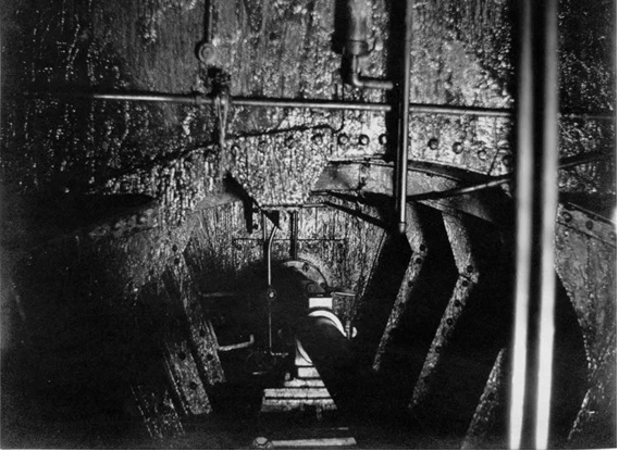
Photo Source: Howard C. Fisher and Philip E. Young, Thesis, Service Test on Steamship Harvard (Parsons Turbine) Power and Speed (Cambridge, MA: Massachusetts Institute of Technology, May 1909). End Notes 1 The Nautical Gazette, “New American Turbine Steamers Yale and Harvard,” The Nautical Gazette 73, no. 6 (August 8, 1907): 79; International Marine Engineering, “S.S. Great Northern and Northern Pacific,” International Marine Engineering 19, no.12 (December, 1914): 536.
2 Denis Griffiths, Steam at Sea: Two Centuries of Steam Powered Ships (London, Great Britain: Conway Maritime Press, 1997), 142.
3 U.S. Naval Institute, Naval Machinery (Annapolis, MD: U.S. Naval Institute, 1941), Part IV, 36.
4 Denis Griffiths, 140.
5 U.S. Naval Institute, Naval Machinery (Annapolis, MD: U.S. Naval Institute, 1941), Part IV, 3.
6 Ibid., Part IV, 3-4.
7 Edwin L. Dunbaugh, The Era of the Joy Line: A Saga of Steamboating on Long Island Sound (Westport, CT: Greenwood Press, 1982), 277; The Nautical Gazette, 82;
8 For an good operational history of these vessels see the following source:
George F. Gruner, The White Flyers (San Francisco, CA: : Associates of the National Maritime Museum Library at The Glencannon Press, 2002).
9 For an good operational history of these vessels see the following source:
John R. Emery, “Fleet Flagships: The Story of the Great Northern and the Northern Pacific,” Steamboat Bill 64, no. 3 (Fall, 2007): 5-21.
10 The Nautical Gazette, 83.
11 International Marine Engineering, 540.
12 The Nautical Gazette, 79.
13 International Marine Engineering, 535.
14 Robert M. Neilson, The Steam Turbine (London, Great Britain: Longmans, Green, and Co.), 513-514.
15 Robert M. Neilson, The Steam Turbine (London, Great Britain: Longmans, Green, and Co.), 516-518. [Note: This description refers to Turbinia with multiple screws per shaft. Later practice reduced this to a single screw per shaft, but the practice of one turbine per shaft remained until the abandonment of direct drive turbines.]
16 Giles T. Brown, Ships That Sail No More: Marine Transportation from San Diego to Puget Sound, 1910-1940 (Lexington, KY: University of Kentucky Press, 1966), 3.
17 Denis Griffiths, 142.
18 Ibid.
19 C.M. Parsons and R.J. Walker, “Development of the Marine Steam Turbine,” The Marine Review 35, no. 5 (January, 1907): 26.
20 G.J. Giles Lieutenant Commander U.S. Navy, Steam Turbine: A Treatise Covering U.S. Naval Practice (Annapolis, MD: United States Naval Institute, 1917), 74.
21 Ibid.
22 E.M. Speakman, “The Determination of the Principal Dimensions of the Steam Turbine with Special Reference to Marine Work,” International Marine Engineering 11 (February, 1906): 56-57; C.M. Parsons and R.J. Walker, 25.
23 C.M. Parsons and R.J. Walker, 25.
24 E.M. Speakman, 57.
Bibliography Primary Sources Books Meyers, G.J. Steam Turbines: A Treatise Covering U.S. Naval Practice. Annapolis, MD: United States Naval Institute, 1917. Naval Machinery. Annapolis, MD: United States Naval Institute, 1941. Neilson, Robert M. The Steam Turbine. London: Longmans, Green, and Co., 1908. Romig, D.K. The United States Ship Great Northern: History of a Troop Transport.Eagle Press, 1919. United States Navy. Fireman: NAVEDTRA 10520-H. Washington, DC: United States Government Printing Office, 1987. Periodicals Canada, A.B., Commander, U.S.N. "The Turbine Steamship Victorian." 17, no. 2 (May, 1905): 410-427. "S.S. Great Northern and Northern Pacific: New 23-Knot Turbine Passenger Ships Built at Cramp's for the Spokane, Portland &Seattle Railway Company." International Marine Engineering 19, no. 12 (Dec., 1914): 535-545. "Turbine Steamer Governor Cobb." The Marine Review 35, no. 1 (Cleveland, Jan., 1907): 46-47. "Launch of the American Turbine Steamship Yale." The Nautical Gazette 71, no. 23 (Dec. 29, 1906): 385-389. "Launch of the New American Turbine Steamship Harvard." The Nautical Gazette 72, no. 6 (Feb. 7, 1907): 165-167. "New American Turbine Steamers Yale and Harvard." The Nautical Gazette 73, no. 6 (Aug. 8, 1907): 79-90. Parsons, C.A. and R.J. Walker "Development of the Marine Steam Turbine." International Marine Engineering 11 (Dec., 1906): 476-480. -----------, "Development of the Marine Steam Turbine." The Marine Review35, no. 5 (Cleveland, Jan. 31, 1907): 22-26. Peabody, C.H. (Prof.);W.S. Leland (Esq.);&H.A. Everett (Esq.) "Service Test of the Steamship Harvard (Parson's Turbine)." Transactions of the Society of Naval Architects and Marine Engineers 16 (1908): 167-186. Speakman, E.M. "The Determination of the Principle Dimensions of the Steam Turbine with Special Reference to Marine Work." International Marine Engineering 11 (Feb., 1906): 50-58. Scholastic Davis, John F. and Carleton W. Hubbard, Thesis. Service Test of the Steamship Harvard. Economy. Cambridge, MA: Massachusetts Institute of Technology, May, 1909. Fisher, Howard C. and Philip E. Young, [Thesis] Service Test on Steamship Harvard (Parson's Turbine) Power and Speed. Cambridge, MA: Massachusetts Institute of Technology, 1909. Secondary Sources Books Brown, Giles T. Ships That Sail No More. Lexington, KY: University of Kentucky Press, 1966. Dunbaugh, Edwin. The Era of the Joy Line: A Saga of Steamboating on Long Island Sound. Westport, CT: Greenwood Press, 1982. Griffiths, Denis. Steam at Sea: Tow Centuries of Steam-Powered Ships. London: Conway Maritime Press, 1997. Gruner, George F. The White Flyers. San Francisco, CA: Associates of the National Maritime Museum Library at The Glencannon Press, 2002. Periodicals Emery, John R. "Fleet Flagships: The Story of the Great Norther and the Northern Pacific." Steamboat Bill 64, no. 3 (Fall, 2007): 5-21. Russell, John Wright "Greyhound of the Pacific: Saga of the H.F. Alexander, ex-Great Northern Part 1." The Sea Chest 30, no. 1 (Sept. 1996): 3-25. Russell, John Wright "Greyhound of the Pacific: Saga of the H.F. Alexander, ex-Great Northern Part 2." The Sea Chest 30, no. 2 (Dec. 1996): 67-83. THE END |
Last updated: March 16, 2016