Last updated: April 7, 2025
Article
Dendrogeomorphological Analysis of Earthwork Stability at Poverty Point SHS, Louisiana
Grant #: MT-2210-11-NC-09
Principal Investigator: Diana Greenlee
Recipient: University of Louisiana at Monroe, Poverty Point Station Archaeology Program
Contributors: David W. Stahle, Jesse R. Edmondson, and Daniel K. Stahle
Published: 9/30/2013
List of Figures
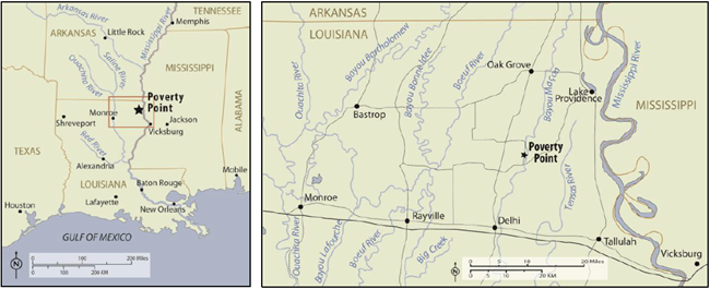
- Location of Poverty Point State Historic Site in northeast Louisiana.
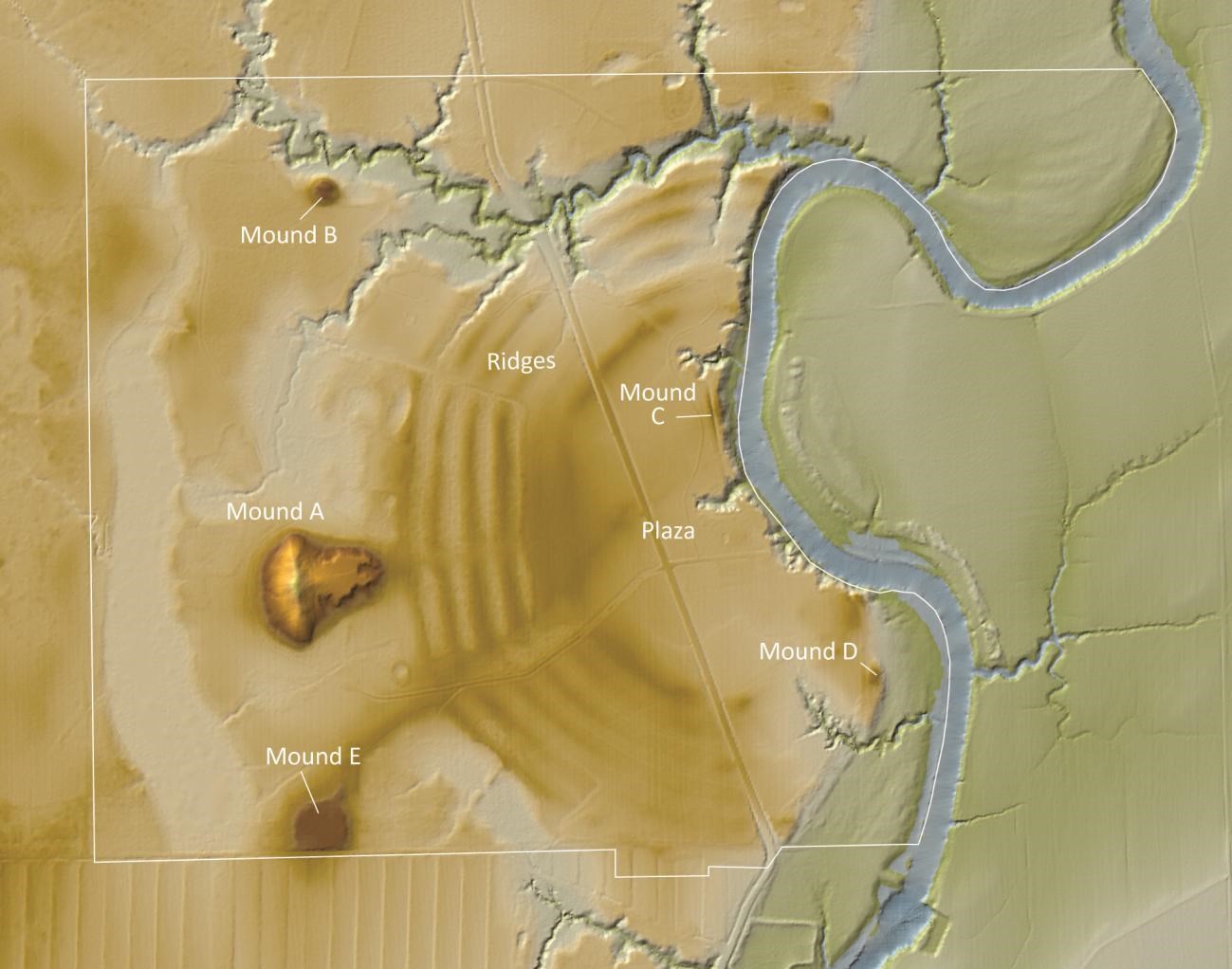
- LiDAR map of Poverty Point, with earthworks labeled.
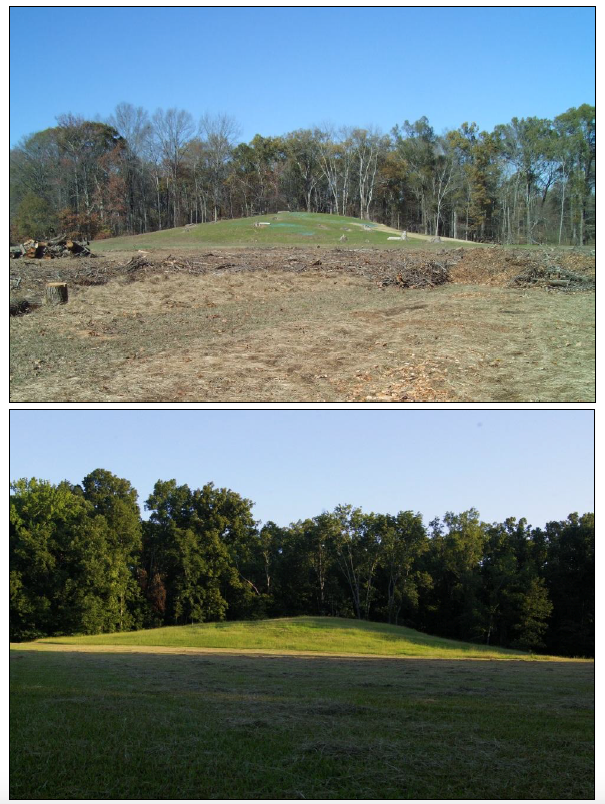
- Top: Photograph of the apex of Mound A in 1993, with exposed roots indicative of 9 significant sheet erosion. Bottom: The apex of Mound A in September 2013.
- Above: Mound B with jute and excelsior blankets and sprouting rye grass in December 11 2010. Below: Mound B under a thick coat of grass in August 2013.
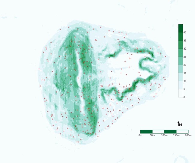
- Distribution of trees removed from Mound A at Poverty Point. Base map shows terrain 12 slope (%).
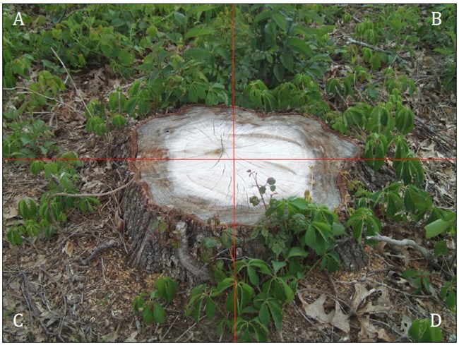
- Quadrant system for counting exposed roots. A and B quadrants are upslope of the 13 stump, and C and D quadrants are downslope from the stump.
- Sanded and tree-ring dated white oak cross sections from Poverty Point.
- Map of Mound A showing locations of exposed roots removed for 15 dendrogeomorphological analysis.
- Jessie Edmondson using a chainsaw to remove a cross section of an exposed root on 16 Mound A.
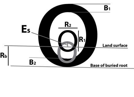
- Schematic diagram of a root cross section with the measurements used to calculate the 16 amount of total soil lost.
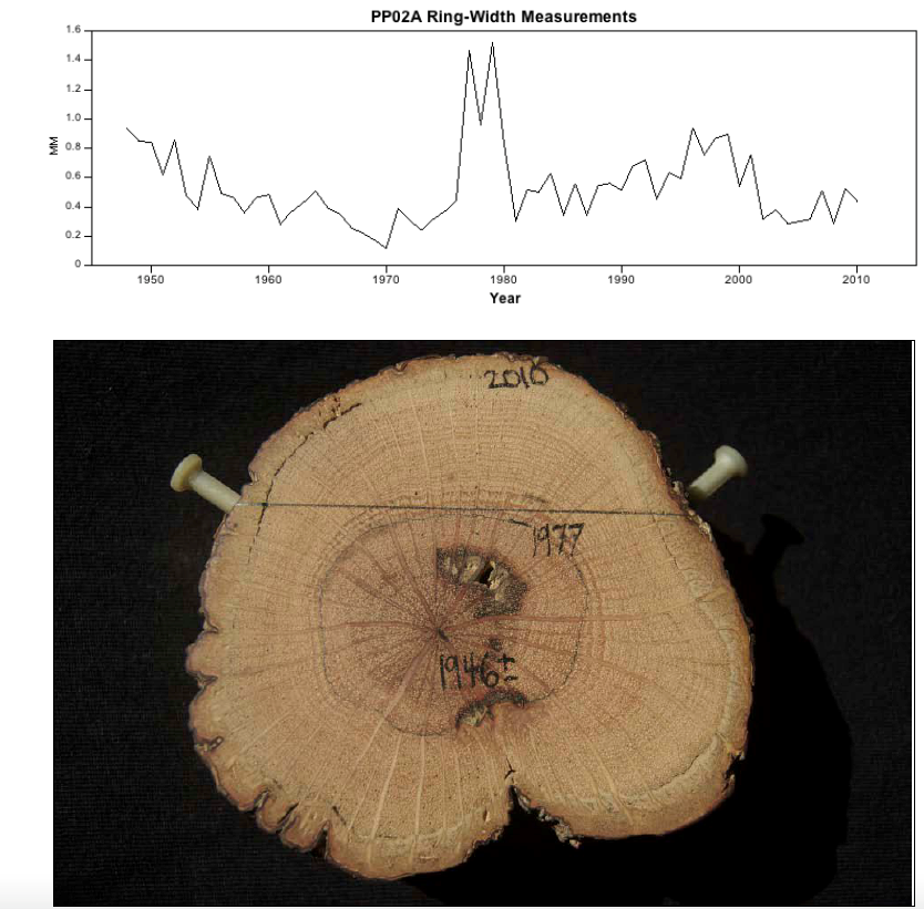
- Raw ring-width measurements are plotted for white oak root sample PP02A (graph at 18 top, in mm). Note the surge in ring widths that mark 1977 as the year of exposure. This is also apparent in the photo below.
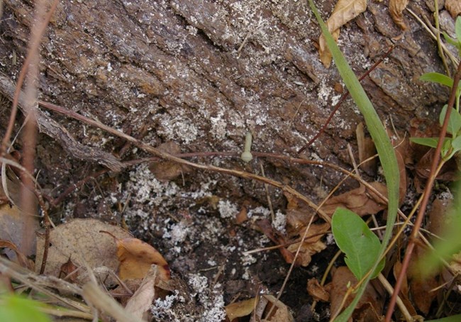
- Stump (root flare) with polymer nail marking the location of the stump/ground surface 19 intersection at the beginning of project.
- Number of windthrown trees per year at Poverty Point State Historic Site.
- Frequency of 179 cut trees on Mound A by approximate year of germination.
- The individual dated ring-width time series (black lines) are plotted with their mean (red 22 line).
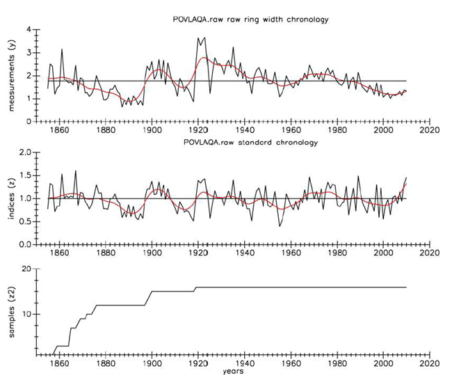
- The mean ring-width chronology for the sixteen white oak series from Mound A Poverty 23 Point is plotted from 1855-2010.
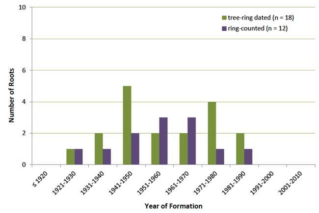
- Year of formation for thirty exposed roots as determined through tree-ring crossdating 24 with the Poverty Point chronology and/or ring-counting.
- Year of exposure at the surface of Mound A for forty-six roots obtained for 25 dendrogeomorphological analysis.
- The distribution of calculated Es values for fifty-two exposed roots taken from Mound A 25 and nearby flat areas.
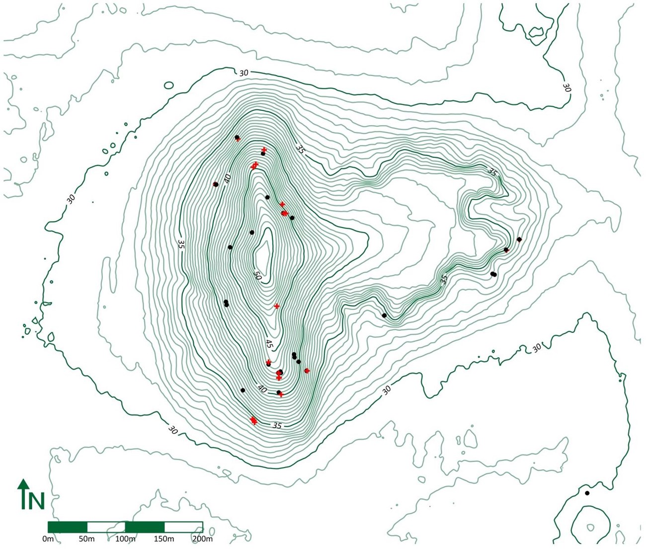
- Distribution of exposed roots on Mound A, classed by soil gain (+) and soil loss (•).
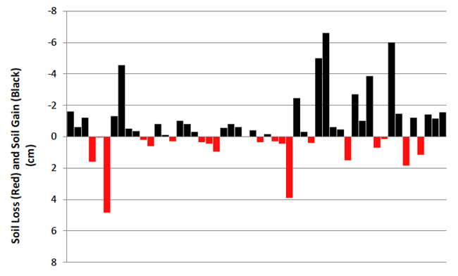
- Rate of soil loss per root sample by year of exposure.
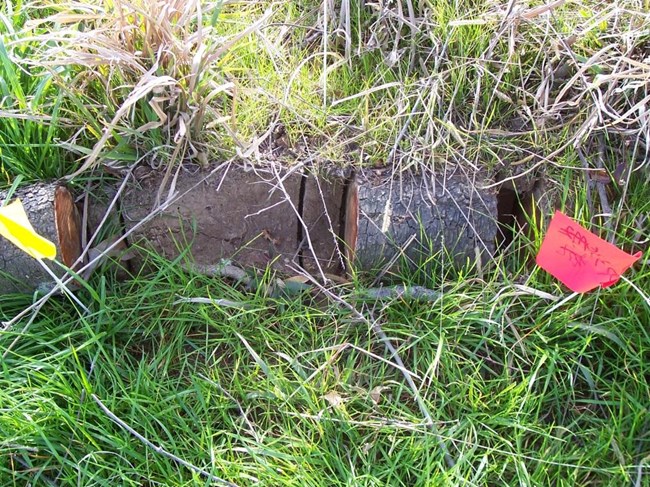
- Exposed root on Mound A with a perpendicular orientation to the slope that has been 29 sampled for geomorphological analysis.
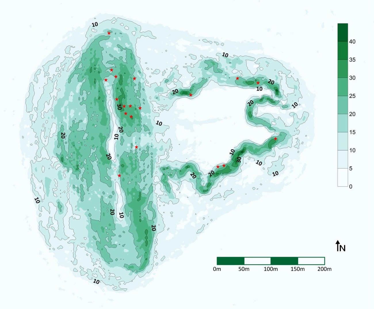
- Slope map of Mound A, showing distribution of trees exhibiting colluvial damming.
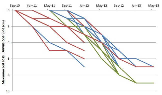
- Soil loss data as measured for nails placed in the downslope side of stumps on mounds 31 A, B and C.
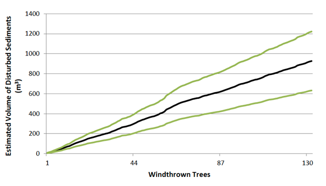
- Estimated cumulative volume (average ± 95% confidence interval) of sediments that 33 would be disturbed as trees are selected by random number generator to be “uprooted."
Executive Summary
In August 2010, the Louisiana Office of State Parks began removing the trees from the earthen mounds at Poverty Point State Historic Site in northeast Louisiana in order to establish a grass cover on the earthworks. This was done for reasons of preservation (primarily to eliminate the threat of windthrown trees) and to provide a more authentic visitor experience (there were no trees on the mounds when they were built). This provided a unique opportunity to use dendrogeomorphology (the study of surface processes using tree rings) to investigate the stability of the earthworks under different vegetation regimes.
The study began with a thorough documentation of the tree stumps and attributes that might reflect past soil erosion (e.g., the location and length of exposed roots, and the presence of colluvial damming). Cross-sections from twenty white oak trees were taken to establish a master tree-ring chronology for Poverty Point that could be used to establish the age and exposure date of the tree roots. One hundred cross-sections of exposed tree roots were taken for dendrogeomorphological analysis to determine when they were exposed to air and how much soil had been lost since that time. Unfortunately, the results were not conclusive – there were more cases of apparent soil gain than loss – but that was probably due largely to sampling issues. Analysis of the other attributes indicated that significant soil erosion had occurred in the past.
The study next documented erosion after the trees were cut down and while a grass cover was being established. The soil-wood interface on tree stumps was marked with nails and the nails were used to measure soil loss. Soil loss occurred, but it is not yet clear how the current erosion rate compares to historic rates.
Finally, characteristics of trees previously uprooted on the site were used to predict how much the earthworks might have been disturbed by windthrown trees, if trees had been left on the mounds. Using the strong relationship between a tree’s stem size and the amount of dirt disturbed when it is uprooted, a conservative estimate is that nearly 1,000 m3 would have been disturbed if the trees remained, indicating that removing the trees prevented significant damage to Mound A.
Together, these data provide a baseline against which future erosion of the earthworks can be compared and this project could provide a framework for evaluating similar management decisions at other earthwork sites.
Introduction
Erosion poses a significant challenge to the management of earthen landscapes, particularly where there are steep slopes. In the absence of protective cover, raindrops hitting the bare soil will dislodge soil particles. Surface runoff from excess precipitation will transport those particles downslope. Sheet erosion occurs when surface runoff is not a concentrated flow; when the runoff is defined, rills and gullies will be created. Water that infiltrates the ground may run in voids or pipes, eroding the structure internally and eventually causing slope failure. A thick plant cover that intercepts raindrops before they reach the ground and that has a dense system of roots, which increase both the soil’s capacity to absorb water and the mechanical strength of the soil, is critical to protecting earthen landscapes (Simon and Collison 2002).
Forests are argued by some to offer the greatest protection for earthworks (Andropogon Associates, Ltd. 1989; Johnson 1998). Likewise, some guidelines for managing historic and prehistoric earthworks advise that continuous grass and/or herbaceous plants are the most desirable ground covers (United States Department of the Interior 2005). The current debate over the impact of vegetation on the integrity of artificial levee systems managed by the United States Army Corps of Engineers is indicative of the lack of consensus about the issue (Corcoran et al. 2010). There are clear advantages and disadvantages to either regime, but it appears that, as long as the existing vegetation cover is in good condition (Table 1), there is no necessary reason to convert from one to the other. Indeed, it is considered risky to switch between them (Andropogon Associates, Ltd. 1989; United States Department of the Interior 2005). This is because bare soil is a likely, if only short-term, outcome that could leave an earthwork vulnerable to erosion.
Diana Greenlee, University of Louisiana at Monroe
Poverty Point State Historic Site
The Poverty Point archaeological site, located in northeast Louisiana (Figure 1), is a monumental earthworks site dating to 3700-3100 years BP. The original site plan (Figure 2) included four earthen mounds; six concentric, semi-elliptical earthen ridges; and a large, flat, interior plaza that contained large circles of wood posts. A fifth mound was added by a later culture in about 700 AD. The massive scale and elaborate design of this created landscape makes it unique in the world. That it was built by hunter-gatherers without the benefit of domesticated animals or wheeled carts renders it truly remarkable.
Diana Greenlee, University of Louisiana at Monroe
Forty years later, the forest cover on the mounds at Poverty Point ranked somewhere between fair and poor according to Table 1. Large, mature trees of roughly the same age covered the earthworks. The tree canopy was not continuous, however, and it was not entirely effective at intercepting heavy rain, particularly since most rain occurs between October and April when deciduous trees are bare; heavy summer showers overwhelmed the canopy (c.f., Simon and Collison 2002). Ground cover was spotty and bare spots were visible. Animal burrowing was present and the trees were increasingly susceptible to windthrow.1

Kevin L. Jones/New Zealand Winston Churchill Trust
After the trees were cut on each mound, and even before clean-up was complete, all bare areas were covered with woven jute or excelsior erosion blankets and seeded with rye grass, which sprouted quickly and helped to stabilize the mound surfaces during the first winter (Figure 4). Small rolls of excelsior blankets were employed as debris dams on the steepest slopes. All stumps were to be trimmed to 1-2” above ground surface to allow mowing equipment to pass over them; most, except those on the steepest slopes, were leveled with a stump-grinder. Debris clean-up and stump trimming was completed for all mounds in February 2012. A thick growth of native grasses and herbaceous plants has largely taken over the mounds.
Footnotes
1Windthrown or uprooted trees pose the greatest threat to earthworks under forest cover (Johnson 1989). Older, larger trees with heavy crowns are more at risk for windthrow (Shaetzl et al. 1990; Stathers et al. 1994; Stokes 1999; Clinton and Baker 2000) and will create more damage than younger, smaller ones (Lenart et al. 2009). The uprooted root plate, or rootball, disturbs the soil of the earthwork and, if the fallen tree was on a slope, it can destabilize the soil and allow sediment to be transported downslope (Shaetzl et al. 1990; Gabet et al. 2003).
2Since 2006, the areas impacted by these efforts been fully documented by mapping the ground surface before and after filling.
Diana Greenlee, University of Louisiana at Monroe
Investigating Mound Stability: Past, Present, Future
Removing the trees presented an opportunity to study historic rates of erosion of the mounds, to provide a quantitative assessment of how this change in vegetative regime might impact the mounds, and to compare those estimates with potential damage caused by uprooted trees, had they not been removed. Although the project was designed to take advantage of this unique situation, it was also constrained by management requirements. Management concerns necessarily took priority over research, as the stability of the earthworks was the over-riding concern.Dendrogeomorphology, the study of surface processes using tree rings, provides an elegant way to estimate past soil loss rates on a wooded slope. Although there are a variety of applications for dendrogeomorphology, the most appropriate method for our purposes uses exposed tree roots to estimate rates of sheet erosion over the lifetime of the root (e.g., Gärtner 2007; Bahrami et al. 2011). This is possible because the growth patterns of tree roots change when the roots are exposed to air. By identifying and dating the onset of those anatomical reactions and establishing how much soil has been lost since the roots were exposed, the rate of sheet erosion can be calculated. Establishing a master tree-ring chronology for Poverty Point using cross-sections from the felled trees will allow the roots to be cross-dated for a more precise age determination than simply counting rings would permit. Colluvial damming and the pattern of exposed roots around each stump are other potential, albeit less precise, indicators of erosion history that were also investigated.
The change from a wooded to a grassy cover presented an opportunity to measure how much erosion took place during that transition. The tree stumps themselves, because they were to be left in the ground and could be easily relocated, were used as natural benchmarks. The intersection of tree stem and/or roots with the ground surface for a sample of stumps was carefully marked and monitored to record changes in the land surface.
Diana Greenlee, University of Louisiana at Monroe
Materials and Methods
As the trees were removed, each stump was numbered with indelible ink3 and located using a Trimble GeoXT handheld GPS so that maps could be generated of the former distribution of trees on the four mounds (Figure 5). Stump diameter and height above ground surface were recorded. Wood wedges were obtained from a sample of trees for later taxonomic identification. Most of these basic field data were collected as the trees were cut, but that was not always possible due to safety concerns or scheduling conflicts.
Diana Greenlee, University of Louisiana at Monroe
Footnotes
3 The ink was not entirely indelible, as the herbicide sprayed on the stumps to inhibit regrowth apparently dissolved it.
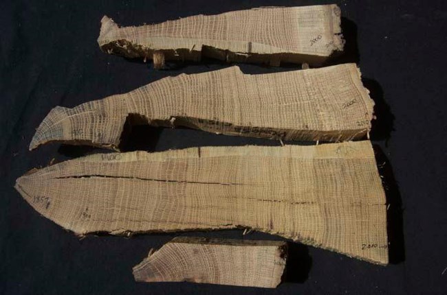
Cross sections of wood from poverty point, sanded and three tree-ring dated white oak samples shaped like axe-heads at the top and a doorstop-shaped one at the bottom.
Diana Greenlee, University of Louisiana at Monroe
Tree-Ring Sampling
Sixteen stem cross sections for tree-ring dating were obtained from a subset of the white oak trees felled on Mound A. The stem cross sections were returned to the University of Arkansas Tree-Ring Laboratory where they were sanded to a fine polish to expose the wood anatomy (Figure 7). As described by Stahle et al. (2013:5-6):
The white oak cross sections were crossdated with each other using the skeleton plot method to account for missing or false rings (Stokes and Smiley 1995). A composite chronology was developed for the Poverty Point white oak specimens and was then compared to pre-existing chronologies in the region to confirm the exact calendar dating of all rings. The dated ring widths on the Poverty Point white oak specimens were measured to 0.001 mm precision. The exactly dated ring-width measurements were submitted to the quality control program COFECHA (Holmes 1983) to statistically verify the crossdating. Using the program ARSTAN (Cook and Peters 1981; Cook et al. 2007), the raw measurements were detrended using a spline curve with a 50% frequency response of 50 years, the ring-width indices were computed by division of the measured ring-width value by the value of the fitted curve for each year, and the numerical ‘standard’ chronology was computed as the robust mean of all available ring-width indices each year. Finally, the variance of the derived chronologies was stabilized using a smoothing spline with a 50% frequency response of 100 years.

LSU CADGIS Research Laboratory
Root Sampling
Cross sections of exposed roots were acquired from Mound A (Figure 8). Each was extracted with a chainsaw (Figure 9). Prior to sampling, the soil contact locations on both sides were marked with acrylic polymer nails. In some cases, sediments encasing the bottom of the root cross sections were excavated before taking the sample; the disturbed area was documented (width, length and depth) and sediments were replaced after the sample was taken. Each root cross section was labeled, the soil contact locations were marked in ink as a backup to the nails, and other information (e.g., distance from the cross section to the stump, the slope angle and the diameter of the root at the cut) was recorded. A total of 100 root samples were taken from 40 different trees of various genera, including Quercus, Prunus and Carya. Eighty-eight samples were removed from slopes of the mound, while twelve were taken from flat, off-mound contexts. A total station was used to determine the precise location of each root sample and photographs were taken to document the sample context.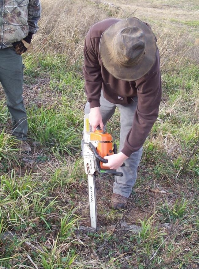
Diana Greenlee, University of Louisiana at Monroe
Multiple measurements were taken from the root samples using a modified version of the method described by Gӓrtner (2007). These measurements and the equation used to compute the total depth of soil eroded from the exposed roots (Es) are described in Figure 10. The root samples with sufficient growth rings for tree-ring crossdating were dated against the master chronology for Poverty Point. When possible, the inner and outer ring dates, and the year of root exposure were exactly dated and labeled on the root samples. The ring-width series on some root specimens were too distorted or otherwise compromised to permit exact dating, but, in many of these cases, approximate dates could be determined using simple ring counts.
Diana Greenlee, University of Louisiana at Monroe
- An increase in ring width at or soon after exposure
- Discoloration of the polished wood at the point of exposure
- A change from more or less diffuse porous to ring porous wood anatomy at the time of exposure (on ring porous species only)
- Thickening of the latewood zone upon exposure, sometimes including tangential bands of fiber cells
- An increase in vessel diameter on recently exposed root wood
- Scarring of the cambium and a wound response on the upper surface of the root near the time of exposure
Diana Greenlee, University of Louisiana at Monroe
Surface Stability Following Tree Removal
Although erosion pinsFootnote 4 are commonly used to measure soil loss (Azola 2001), they were not used here in order to avoid introducing metal onto the archaeological site, especially into an active management zone where they would likely be kicked, run over, or otherwise translocated. Instead, the stumps were used as permanent benchmarks against which soil loss could be measured. Initially, the stumps were scored with a chisel at ground surface, but it was difficult to make a lasting mark that was distinct upon subsequent visits and that would remain distinct as the stumps weathered. Next, orange spray paint was used, carefully masking the ground surface so that paint would not alter the erosional properties of the soil, but the paint began to weather and the line lost its sharpness. Finally, acrylic polymer nails were pounded into the stumps to mark the location of the ground surface at multiple places (Figure 12).
Fifty-two stumps on relatively flat (0 – 10%, n = 19), moderate (10 – 25%, n = 21) and steep (> 25%, n = 12) slopes were marked with nails. The stumps were revisited at four-month intervals and changes in the position of the ground surface relative to the nails were measured to the nearest centimeter. The number of stumps that provided reliable data decreased over time due to a variety of factors, including fire-ant nesting, armadillo burrowing and maintenance activities like stump trimming, stump grinding and weed-eating.
Footnotes
4These pins are essentially metal rods that are inserted into the ground with their heads flush with the surface. The distance between the head and the ground surface increases as erosion occurs.
Diana Greenlee, University of Louisiana at Monroe
Windthrown Trees
Since 1997, the Poverty Point Station Archaeology Program has maintained records for windthrown, or uprooted, trees in the park. These records include the number of downed trees per year (Figure 13) and, for each tree, its location, the dimensions of the rootball (or root plate), the dimensions of the roothole (or pit), and the archaeological impact. The number of windthrown trees appears to be increasing slightly over time, except for those years with catastrophic wind events, such as in the years 1997-1998 and 2010-2011. The high tree casualties in 2010-2011 were almost certainly a result of the tree removal project, which exposed previously sheltered trees to greater wind forces than they were acclimated to (Sellier and Fourcaud 2009). Over the past ten years, there has been a statistically significant upward trend in the number of trees being uprooted each year, excluding the extreme 2010-2011 year (adj. R2 = 0.695; F = 19.201; p =0.003).
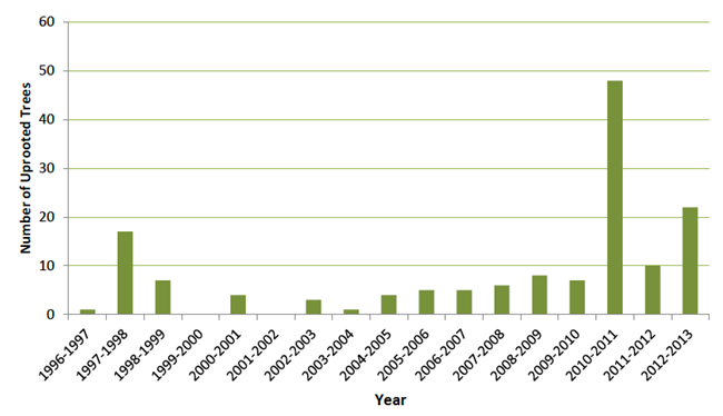
A chart, x axis from 1996-1997 to 2012-2013, y axis as number of uprooted trees. Below 20, then 10, from 1999 forward, grows until 2010-2011, dipping in 2011-2012 to 10, then growing to over 20 in 2012-2013.
Diana Greenlee, University of Louisiana at Monroe
Root architecture and stem characteristics are both important factors in determining the amount of disturbance caused by an uprooted tree, and these variables will differ among species. Several of the previously uprooted trees were revisited and thirty-two wood samples were obtained for taxonomic identification by Ms. Andrea Shea Bishop. There was so much variation in the characteristics of those windthrown trees, however, that no taxon-specific differences were observed for that small sample.
Because the amount of soil disturbance is correlated strongly with tree size (Lenart et al. 2009), stem circumference or diameter was also measured for twenty-four windthrown trees. The standard location for tree circumference/diameter measurements is breast height (1.4 m), but because the trees which we would like to model were stumps at a range of heights, the circumference of the windthrows was measured at the average height of the stumps on Mound A when their diameters were measured (approximately 42 cm). Stem diameter was found to correlate significantly with the calculated volume5 of the uprooted sediments (adjusted R2 = 0.642; F = 43.238; p < 0.001). Stem diameter is used as a coarse estimate of the damage that a windthrown tree can do.
5The roothole volume was calculated as an elliptical area (π × (roothole width × roothole breadth)/4) and multiplied by rootmass depth.
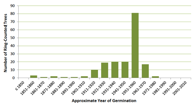
A bar chart in green, x axis from 1850 to 2010, and y axis for Number of Ring-Counted Trees. Numbers remain low 1851-1910, 20 from 1921-1950, 80 from 1951-1960, 10 for 1961-1970, a few in the 70s, and none to 2010.
Diana Greenlee, University of Louisiana at Monroe
Results and Discussion
Historic Soil Loss
Ring-Counted Estimates of Tree Age
Ring-counted age estimates were obtained from 179 tree stumps on Mound A. The trees ranged in age from 40 to 156 years at the time they were cut, with an average age of 67.2 years (Stahle et al. 2013). Because the rings were so well-defined and the stumps were cut very near the ground surface, the ring-counted ages are likely close to the true germination age of these trees. Figure 14 plots the trees on Mound A according to their approximate year of germination. These data are consistent with descriptions of how the forest cover on the mounds was managed. It is clear this was not a mixed-age stand that would characterize a stable forest.

Diana Greenlee, University of Louisiana at Monroe
Tree-Ring Dating
A master tree-ring chronology for Poverty Point was successfully derived from the sixteen white oak cross sections taken from Mound A trees. Stahle et al. (2013:7) described the results:
The individual chronologies for sixteen tree-ring dated white oak radii (all probably Quercus alba) are plotted in Figure 15 and illustrate the strong crossdating of interannual ring-width variability among these sample trees and radii. The standard tree-ring chronology derived for white oak at the Poverty Point site is plotted from 1855 to 2010 in Figure 16. The radial growth of most upland oak species in the southcentral United States tends to be positively correlated with precipitation and negatively correlated with temperature during the growing season (Blasing et al. 1988; Stahle and Cleaveland 1988; Haavik et al. 2011). The tree-ring chronology developed for white oak at Poverty Point is correlated with other oak chronologies from Arkansas (e.g., r = 0.43 for a comparison between the Poverty Point and Lake Winona, AR, white oak chronologies for the period 1901-1980). We have not specifically modeled the climate signal in the white oak chronology from Poverty Point, but the chronology certainly records some of the major droughts that afflicted northeast Louisiana during the 20th century (e.g., 1918, 1925, 1955, 1956, 1988, 1998, and 2000; Figure 6; growing season droughts identified in the instrumental Palmer Drought Severity Indices for Louisiana Climate Division 2, National Climatic Data Center, NOAA).
Diana Greenlee, University of Louisiana at Monroe
Dating Exposed Roots
The ages of eighteen roots acquired for dendromorphological analysis were exactly determined by crossdating with the 156-year long Poverty Point tree-ring chronology (Figure 17). Twelve additional roots were aged using ring counts. The dates range over 64 years, from 1923 to 1987. Eighteen tree-ring dated roots may not sound like a significant accomplishment, but, according to Stoffel et al. (2013), roots have never been successfully crossdated before. Without the ability to use tree-ring chronologies to date dead roots, studies of erosion history have been constrained to living roots.
Alternate Text for Figure 16
A series of three charts with the years along the x axis, and on the y axis: measurements (first chart), indices (second chart), and sample size (third chart, shows samples).
The mean ring-width chronology for the sixteen white oak series from Mound A Poverty Point is plotted from 1855-2010 (top plot, in mm, without any detrending or standardization).
The standardized ring width chronology for Poverty Point is plotted in the middle time series, after detrending and standardization (achieved by fitting a smoothing spline with a 50% frequency response of 50 years to the raw measurements and dividing the measured ring width value by the value of the fitted curve at each year [Cook and Peters 1981; Cook et al. 2007]).
The sample size for each year is plotted in the bottom series (i.e., the number of dated radii per year). Drought years and poor growth are indicated in the middle plot by values below the mean of 1.0, wet years and favorable growth by values above the mean. Note the low growth in 1918, 1925, 1943, 1954-56, 1985, 1988, 1998 and 2000.
Diana Greenlee, University of Louisiana at Monroe
Exposed Roots and Soil Loss
Dendrogeomorphology
Most of the 100 exposed roots collected on and around Mound A were not useful for examining erosion history because they had multiple piths or severe scarring, did not display a clear reaction to surface exposure or were missing wood. Soil loss could be calculated using Equation (1) for fifty-two roots; of those, the year of exposure was determined for forty-six. Es, the amount of eroded soil, is positive when soil has eroded around the exposed root. Negative values of Es indicate that soil has accumulated around the exposed root; the most likely scenario for this situation is that, once exposed, the root continued to grow out of the ground and served as a dam or sediment trap. Figure 19 plots Es for the root samples. More exposed root samples exhibit soil gain rather than loss, and the average amount of soil gained is greater than the average lost (1.5 vs. 1.06 cm).
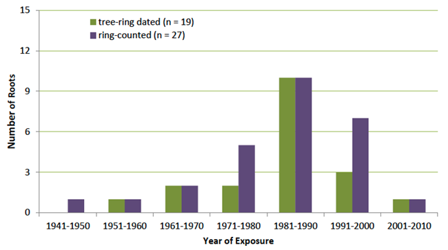
Both tree-ring dated and ring-counted dated roots peak in the 1980s at 9.
Diana Greenlee, University of Louisiana at Monroe
Diana Greenlee, University of Louisiana at Monroe
Diana Greenlee, University of Louisiana at Monroe
Stahle et al. (2013) suggest that there may be a species effect on the soil loss/gain results. They found that the most negative (soil gain) estimates were associated with white oak roots, while the most positive (soil loss) calculations were associated with roots of other species.
They note that the sample size is too small for a rigorous test of that hypothesis, but that future experiments might allow determination of which species are best suited for using exposed roots to estimate soil erosion. Certainly, most of the published research has relied on Pinus species.
A recent review by Stoffel et al. (2013) on using exposed roots to study erosion processes noted four factors that were not taken into account when this aspect of the research was designed:
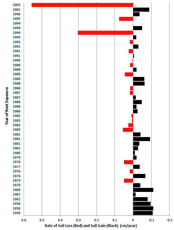
From 1949 to 2003, the rate of soil gain is under 0.1 cm, with peaks at 0.1 cm generally declining in the 1970s, 80s, picking up in 1981 and 2001. Soil loss in red is under 0.1 cm until 1994, at
Diana Greenlee, University of Louisiana at Monroe
- Recent research indicates that roots may show anatomical responses to exposure while they are still buried as much as 3 cm below the surface (Corona et al. 2011). Until further studies can determine the extent to which this observation for Pinus sylvestris roots is applicable to other taxa, soil loss calculations may be systematically low. A 3 cm adjustment would make a significant difference for this analysis.
- Roots have a sheltering effect on the soil around them. Analyses of surface microtopography reveal sediments higher on the sides of the root and sloping downward to a flat plane with distance from the root. So, using the height of soil directly against the root (root-soil contact) as the measure of current ground surface, as was done here, can lead to a systematic underestimate of the actual amount of soil loss that has occurred. This is particularly true for larger roots (Stoffel et al. 2013).
- Roots oriented at perpendicular or oblique angles to a slope may act as barriers to sediment movement downslope. For this reason, only roots parallel to the slope should be used for erosion studies. This research included roots from a variety of orientations (Figure 22).
- Root samples should be taken at distances at least 0.5 to 1.0 m away from the trunk base to avoid potential influence of the stem on the roots (e.g., upward pull on the roots by movement of the stem) that could introduce noise into the analysis. Fourteen samples were within 0.5 m and forty-nine samples were within 1.0 m from the stump.
Diana Greenlee, University of Louisiana at Monroe
These confounding factors noted by Stoffel et al. (2013) are likely to have the greatest impact in situations where soil loss rates are relatively modest. The first three factors almost certainly will combine to produce underestimates of soil erosion. Thus, our seemingly equivocal results are probably the result of the research design, which, of course, predates the sampling guidelines of Stoffel et al. (2013). Clearly, although dendrogeomorphology did not provide the information we hoped it would regarding soil loss on Mound A in this instance, this does not mean that it cannot be successfully applied to archaeological landscapes that are under threat of erosion.
Diana Greenlee, University of Louisiana at Monroe
Quadrant Analysis
The number of exposed roots counted within quadrants A-D (see Figure x for layout) for each of the 205 stumps examined for exposed roots on Mound A are presented in Table 2. Most (74.3%) of the exposed roots were found in quadrants C and D, located downslope from the associated stump. A one-tailed paired-sample t test comparing the root counts for the upslope (A + B) quadrants versus the downslope (C + D) quadrants for all trees indicates significantly fewer roots were counted in the upslope than downslope quadrants at α = .05 (t0.05,1,204 = 1.652; t = -11.322; p =1.12 × 10⁻²³).
Similarly, the longest exposed root for each tree examined on Mound A was identified by quadrant. The overwhelming majority (85.71%) were located in the downslope quadrants. A one-tailed two sample t test (assuming unequal variances) comparing the lengths of the longest exposed roots for the upslope (A + B) versus the downslope (C + D) quadrants indicates significantly longer roots are exposed in the downslope quadrants at α = .05 (t0.05,1,142 = 1.656; t = -1.890; p =0.030).
These data are consistent with soil accumulation on the upslope side (quadrants A and B) of tree stems due to colluvial damming. At the same time, erosion on the downslope side (quadrants C and D) would lead to exposure of more roots below the tree stems. Stahle et al. (2013) suggest an alternate hypothesis that root growth out of the ground on the downslope surface might be more vigorous as a buttress or reaction wood response to the steep slopes.
Colluvial Damming
The final data set relevant to understanding the erosion history of Mound A at Poverty Point draws on observations of uneven slope surrounding the cut tree stems. On some stumps, there is a gentler slope against the upslope side and a steeper slope leading from the downslope side. This has been attributed to colluvial damming, wherein the tree stem acted as an impediment to the downslope movement of sediment, trapping it upslope of the stem. Erosion was not similarly dampened on the downslope side, allowing a steeper slope to form. It is not surprising that these features appear to be associated with steeper slopes on Mound A (Figure 23).
These features hold some promise for understanding past erosion rates, but it is more complicated than just knowing the age of the tree and the deflection from the mound’s natural slope. Tree growth needs to be modeled because changing stem diameter will impact the amount of sediment held over time; early in the tree’s life, the stem may be too thin to capture sediment and the calculated erosion rate might be underestimated. Determining the amount of accumulated sediment will require both detailed topographic mapping and sediment cores to identify the surface of the mound. One can hope to find lamellar structures or a buried A horizon beneath the dammed sediment, but if it is an erosional surface, the latter may be lacking.
Diana Greenlee, University of Louisiana at Monroe
Surface Stability Following Tree Removal
Figure 24 plots the maximum soil loss measured per stump, coded by slope. As might be predicted from the results of the root exposure/quadrant analysis and the colluvial damming observations (but not anticipated before the experiment began), the downslope nails consistently showed the greatest soil losses, whereas the upslope nails were relatively quickly covered with sediment and vegetative debris. This, of course, did not happen with nails on flat slopes. The records of the lateral nails varied, depending on whether they were upslope or downslope of roots or lobes in the stem.
There was a steady attrition over time in the number of stumps that were monitored, either because of fire-ant nesting, armadillo burrowing or feeding activities, or maintenance activities. Stump grinding and weed-eating around the stumps to rid them of shoots were probably the two key maintenance activities that resulted in the loss of nails.
One of the drawbacks to this method of erosion monitoring is that the results are not directly comparable to other methods. The nails record soil loss at a single point along a small erosional front, the downslope side of the stump, and the sediments presumably disperse and are dropped as they encounter other vegetation. Erosion pins are generally not set at a defined front of erosion, but record soil loss within a greater plot where sheet erosion may be taking place. Thus, erosion pin studies record soil loss in mm/yr, not cm/yr as reflected by the nail-marked stumps. Future exploration of soil loss rates using models like the Revised Universal Soil Loss Equation (United States Department of Agriculture 2012) or the Guide for Predicting Sheet and Rill Erosion on Forest Land (Dissmeyer and Foster 2004) may be useful for putting these results into context.
In retrospect, a better understanding of the impact of strong rain events on soil loss would have been gained had the nails been checked after significant storms, rather than every four months. This would require much more time, as the precipitation records from nearby Tallulah, LA, indicated thirty-six major rain events (> 3.0 cm within 24 hours) throughout the duration of the study.
Diana Greenlee, University of Louisiana at Monroe
Potential Future Damage from Windthrown Trees
Had the trees not been removed from the mounds, it is likely that uprooting would have resulted in significant damage to the mounds. The correlation between stump diameter and roothole volume allows estimation of damage to the mound that could have occurred. Figure 25 models cumulative sediment disturbance as trees on Mound A, up to a 75% sample, selected by a random number generator, are “uprooted.” This estimate does not attempt to deal with the potential impact of erosion beyond the initial windthrows; an uprooted tree on a steep slope may represent an initial erosional scar that can increase greatly in scope.
Conclusions
Removing the tree cover from the earthen mounds at Poverty Point State Historic Site presented an opportunity to investigate the impact of changing vegetation regimes on earthwork stability. Efforts to use dendrogeomorphology to establish past rates of soil loss on Mound A produced inconclusive results. Examinations of the distribution of exposed roots (with more, and longer segments of, exposed roots in downslope quadrants rather than in upslope ones) and the presence of different slopes uphill and downhill from the tree stems (suggesting that sediments are trapped above the tree) were consistent with previous observations about erosion on Mound A. However, it was also hypothesized that these patterns could be reflecting tree growth processes. On a positive note, root age and exposure year were successfully determined by crossdating them with the Poverty Point tree ring chronology, a feature lacking in previous dendrogeomorphologic analyses.
Soil loss following the removal of trees from the mounds was monitored using the stumps as control points. The pattern of sediment movement observed (soil gain on the upslope and soil loss on the downslope of stumps) supported the hypothesis that the trees were acting as colluvial dams to stop the downslope movement of sediments. Unfortunately, the rate of soil loss after tree removal cannot be readily compared with soil loss rates prior to tree removal. This might be investigated in the future by extracting sediment cores from the upslope side of stumps (using stumps that are sufficiently higher than ground surface to continue trapping sediments).
Future refinements to these analyses should provide a clearer assessment of the wisdom in removing the trees from the mounds of Poverty Point and, perhaps, guidance for future decisions of this kind. The Louisiana Office of State Parks is planning to expand the tree removal project to the remaining earthworks at Poverty Point. Given the results of this research, that would appear to be a good management decision.
Acknowledgments
I would like to recognize the Louisiana Office of State Parks for taking the necessary steps to protect the earthworks at Poverty Point State Historic Site. The contractor, Gary Jones, was responsive to concerns about the tree removal process and conducted the work as carefully as possible. The on-site park management staff (Dennis LaBatt, David Griffing, Mark Fox, Bretton Woods and Allen Frey) have worked tirelessly to clean up the mounds after the trees were removed and to minimize soil loss through the use of jute and excelsior erosion blankets and grass seed. They have continued to care for the mounds as native grasses have become established.
I would like to acknowledge the University of Arkansas Tree-Ring Laboratory (David W. Stahle, Jessie R. Edmondson, and Daniel K. Stahle) for their major contributions to the research on past soil loss. Additionally, Andrea Shea Bishop provided taxonomic identifications on wood samples from the cut trees and the treefalls, and Sean Chenoweth donated his time and GIS expertise to the project. The efforts of the Station Archaeology Program staff, Fran Hamilton, Alisha Wright and Meredith Anderson, are much appreciated; their assistance with mapping and windthrow data collection was invaluable.
I would also like to thank the Louisiana Division of Archaeology, the University of Louisiana at Monroe, the National Park Service and the National Center for Preservation Technology and Training for their support of this project.
Finally, I gratefully acknowledge the patient support of my family.
References
Andropogon Associates, Ltd. 1989. Earthworks Landscape Management Manual. Philadelphia, PA.
Azola, Anthony. 2001. The Effect of Management on Erosion of Civil War Battlefield Earthworks. Unpublished Master’s Thesis, Department of Forestry, Virginia Polytechnic Institute and State University, Blacksburg, VA.
Bahrami, Sh., F. Mahboobi, J. Sadidi, and M Fafari Aghdam. 2011. “Estimating the Rate of Sheet Erosion by Dendrogeomorphological Analysis of Tree Roots in Gharechai (Ramian) Catchment.” Physical Geography Research Quarterly 75:18-20.
Blasing, T. J., D. W. Stahle, and D. N. Duvick. 1988. “Tree-ring Based Reconstruction of Annual Precipitation in the South-Central United States from 1750 to 1980.” Water Resources Research 24:163-171.
Clinton, Barton D., and Corey R. Baker. 2000. “Catastrophic Windthrow in the Southern Appalachians: Characteristics of Pits and Mounds and Initial Vegetation Responses.” Forest Ecology and Management 126:51-60.
Constantine, José Antonio, Mart-Jan Schelhaas, Emmanuel Gabet, and Simon Marius Mudd. 2012. “Limits of Windthrow-driven Hillslope Sediment Flux due to Varying Storm Frequency and Intensity.” Geomorphology 175-176:66-73.
Cook, Edward R., and Kenneth Peters. 1981. “The Smoothing Spline: A New Approach Standardizing Forest Interior Tree-Ring Series for Dendroclimatic Studies.” Tree-Ring Bulletin 41:45-53.
Cook, E. R., P. J. Krusic, R. H. Holmes, and K. Peters. 2007. Program ARSTAN, Version 41d, 2007. (www.ldeo.columbia.edu/tree-ring-laboratory)
Corcoran, Maureen K., Donald H. Gray, David S. Biedenharn, Charlie D. Little, James R. Leech, Freddie Pinkard, Pamela Bailey, and Landris T. Lee. 2010. “Literature Review – Vegetation on Levees.” Engineer Research and Development Center, SR 102. Report prepared for U.S. Army Corps of Engineers, Washington, DC.
Corona, Christophe, Jérôme Lopez Saez, Georges Rovéra, Markus Stoffel, Laurent Astrade, and Frédéric Berger. 2011. “High Resolution, Quantitative Reconstruction of Erosion Rates Based on Anatomical Changes in Exposed Roots at Draix, Alpes de Haute-Provence—Critical Review of Existing Approaches and Independent Quality Control of Results.” Geomorphology 125:433-444.
Dissmeyer, George E. and George R. Foster. 1984. A Guide for Predicting Sheet and Rill Erosion on Forest Land. USDA Forest Service, Southern Region, Atlanta, GA.
Gabet, Emmanuel J., O. J. Reichman, and Eric W. Seabloom. 2003. “The Effects of Bioturbation on Soil Processes and Sediment Transport.” Annual Review of Earth and Planetary Sciences 31:239-273.
Gardiner, Barry, Juan Suárez, Alexis Achim, Sophie Hale, and Bruce Nicoll. 2004. ForestGALES: A PC-based Wind Risk Model for British Forests. Version 2.0. Forestry Commission, United Kingdom.
Gӓrtner, Holger. 2007. “Tree Roots—Methodological Review and New Development in Dating and Quantifying Erosive Processes.” Geomorphology 86:243-251.
Haavik, L. J., D. W. Stahle, and F. M. Stephen. 2011. “Temporal Aspects of Quercus rubra Decline and Relationships to Climate in the Ozark and Ouachita Mountains, Arkansas.” Canadian Journal of Forest Research 41:773-781.
Holmes, Richard L. 1983. “Computer-Assisted Quality Control in Tree-Ring Dating and Measurement.” Tree-Ring Bulletin 44:69-78.
Johnson, James E. 1998. “Managing Earthworks under Forest Cover.” Virginia Polytechnic Institute and State University, in association with the National Park Service and the Georgia Trust for Historic Preservation, Blacksburg, VA.
Jones, Kevin L. 1994. “Archaeological Site Stabilisation and Reconstruction in the United States: Winston Churchill Memorial Fellowship Report 1993.” Science & Research Internal Report No. 145, Department of Conservation, Wellington, New Zealand.
Lenart, Melanie T., D. A. Falk, F. N. Scatena, and W. R. Osterkamp. 2009. “Estimating Soil Turnover Rate from Tree Uprooting During Hurricanes in Puerto Rico.” Forest Ecology and Management 259:1076-1084.
Peterson, Chris J., and S. T. A. Pickett. 1991. “Treefall and Resprouting Following Catastrophic Windthrow in an Old-Growth Hemlock-Hardwoods Forest.” Forest Ecology and Management 42:205-217.
Schaetzl, Randall J., Scott F. Burns, Thomas W. Small, and Donald L. Johnson. 1990. “Tree Uprooting: Review of Types and Patterns of Soil Disturbance.” Physical Geography 11(3):277-291.
Sellier, Damien, and Thierry Fourcaud. 2009. “Crown Structure and Wood Properties: Influence on Tree Sway and Response to High Winds.” American Journal of Botany 96:885-896.
Simon, Andrew, and Andrew J. C. Collison. 2002. “Quantifying the Mechanical and Hydrologic Effects of Riparian Vegetation on Streambank Stability.” Earth Surface Processes and Landforms 27:527-546.
Stahle, David W., and Malcolm W. Cleaveland. 2011. “Texas Drought History Reconstructed and analyzed from 1698 to 1980.” Journal of Climate 1:59-74.
Stahle, David W., Jesse R. Edmondson, and Daniel K. Stahle. 2013. “Dendrogeomorphological Investigation of Earthwork Stability at Poverty Point State Historic Site, Louisiana.” Final project report submitted to the Poverty Point Station Archaeology Program, Epps, LA.
Stathers, R. J., T. P. Rollerson, and S. J. Mitchell. 1994. “Windthrow Handbook for British Columbia Forests.” Research Program Working Paper 9401, B.C. Ministry of Forests, Victoria, B.C.
Stoffel, Markus, Christophe Corona, Juan Antonio Ballesteros-Cánovas, and José Maria Bodoque. 2013. “Dating and Quantification of Erosion Processes Based on Exposed Roots.” Earth-Science Reviews 123:18-34.
Stokes, Alexia. 1999. “Strain Distribution during Anchorage Failure of Pinus pinaster Ait. at different ages and tree growth response to wind-induced root movement.” Plant and Soil 217(1-2):17-27.
Stokes, M. A., and T. L. Smiley. 1995. An Introduction to Tree-Ring Dating. University of Arizona Press, Tucson.
United States Department of Agriculture. 2012. “Revised Universal Soil Loss Equation 2.” Agricultural Research Service. Accessed 9 Sept. 2013. http://www.ars.usda.gov/research/docs.htm?docid=6010
United States Department of the Interior. 2005. “05 Currents: Sustainable Military Earthworks
Management.” Accessed 30 April 2010. http://www.nps.gov/hps/hli/currents/earthworks/index.htm
