|
NATIONAL PARK SERVICE
Ruins Stabilization in the Southwestern United States Publications in Archeology 10 |

|
Appendix 2B
USE OF STEEL AND CONCRETE FOR ADOBE WALLS
These records describe the use of steel and concrete to stabilize adobe walls concealed with soil-cement bricks (figs. 65-76).
RUINS STABILIZATION RECORD
FIRST SHEET
Fort Union National Monument. Date: April 29, 1960; Building: 3-440; Room: 443; Feature: Wing walls; Wall (N.E.S.W.): EW.
Architecture
Orientation, plan and type (situation, evidence of additional stories, period of construction relative to surrounding rooms, evidence of burning, etc.): Contemporaneous with contiguous rooms. No evidence of burning. Single story.
Floor (floor type; additional notes): Probably had wood floor.
Details (notes on doorways, lintels, etc.): North and south walls considered as north and south walls of Building 3-440. East wall is west wall of room 442.
SECOND SHEET
Room No.: 3-443; Date work started: June 1, 1957; Date work finished: June 17, 1959; man days of labor: ca. 48-3/4; Cost of materials: ca. $181.72; Archeologist: Rex L. Wilson; date: April 29, 1960.
Condition on date work started. Masonry: Coping on west wall in urgent need of stabilization.
Materials, construction, and technique in making repairs or accomplishing job: West wall: The largest remaining section of brick coping (35' 6" long) on top of 20-foot high walls was completely stabilized with steel, concrete and soil-cement bricks. Eight vertical channels, about 4' to 5' apart, were cut to a depth of about 6" in the east side of the adobe walls supporting the coping. Two additional channels, one directly opposing the other, were cut in the north and south sides of the wall which abuts the coping-bearing wall on the east, and are located about 4' out from the corner formed by the junction of the walls. Horizontal channels were also cut in the west wall, and one on each side of the abutting (east-west) wall, so as to intersect the verticals at regular intervals.
An angle-iron framework, whose components were welded together, was then erected in the channels of both walls. The supporting base plate of 1/8" x 2" strap iron was placed in the lowest horizontal channel of all walls, and rests directly on the rock wall foundations. The vertical members (of 1/8" x 2" angle-iron in the west wall, and 1/8" x 1-1/4" angle-iron in the abutting wall) are supported at their lower ends by the strap iron. All other horizontal members except those at the top of the walls are 1/8" x 3/4" angle-iron.
At the top of that section of coping-bearing wall north of the abutting wall, two horizontal members of 1/8" x 2" angle-iron were welded in place. One is directly opposite the base of the solid brick coping which is present now only on the west side of the wall. The other is immediately below and supports the horizontal veneer of brick which forms the top of this half of the coping, and which extends across the top to the east side of the wall. From the rigid framework on the east side of the wall, 1/8" x 2" modified angle-iron "hooks" extend across the top of the coping and down the west side about 7". These serve to hold the coping in place by preventing it from leaning outward at the top. To prevent the coping from dropping through collapse of the underlying adobe, only an edge of which supports the coping, a 1/8" x 2" angle-iron member was placed horizontally beneath the coping to provide support. It is secured to the framework on the opposite side of the wall by short lengths of 1/2" reinforcing rod, welded in place at each end. The remainder of this half of the framework is secured in a similar manner: an average of 3 short sections of 1/2" reinforcing rod for each vertical member penetrate the wall through drilled holes, and are welded to 6"-long strips of 1/8" x 2" strap iron sunk into the west side of the wall and to the vertical members in the east side.
The top of the wall under the brick veneer cap was almost completely eroded out. The area was cleaned of loose material, squared up and lined with metal lath. It was then rebuilt with soil-cement brick to provide a solid wall between the vertical members and the heavy, solid coping. There are no free-standing (and thus visible) steel members in this part of the wall, and thus maximum rigidity was provided.
The south half of the coping is more massive in construction than the north half, and there is no veneer or brick over the inner (east) portion of the adobe wall. Although the method of securing the coping at the top of the angle-iron framework is similar to that used to support the north half of the coping, more rigid construction was necessary because the vertical supports are free standing for the top 22", approximately. Also, these top sections are offset to the west a distance of 10" from the vertical axes of the lower portions in such a manner as to place the side of the upper portions against the coping.
The free-standing sections overlap the remainder of the vertical supports, and are secured to them by an upper and a lower horizontal member of 1/8" x 2" angle-iron. The rectangles formed were incorporated into the wall proper, by rebuilding this section with soil-cement brick up to and through the rectangles. (The upper sections of wall had eroded out, leaving the coping balanced on just a few inches of adobe.) Two large holes in the wall under the coping were also filled with soil-cement brick.
The free-standing sections of iron (including those portions which overlap the remainder of the vertical sections of the uprights) were further strengthened by welding together two lengths of 1/8" x 2" angle-iron so as to form square members. To these is welded a horizontal member of 1/8" x 2" angle-iron which is cupped over the top (east) edge of the coping, and the 1/8" x 2" strap iron hooks which cross the coping and extend down the west side about 6". The horizontal member under the coping on the east side of the north half of the wall was extended so as to pass under the coping on the south half. Again, it was secured by short lengths of 1/2" reinforcing rod which pass through the wall immediately under the coping, and are welded to the horizontal member on the west side of the wall and to the box members of the east. The rest of the framework was secured by ties through the wall, using 5 sections of 1/2" reinforcing rod to hold each vertical member except the short one over the window (where 3 were used).
Both halves of the framework in the coping-bearing wall are welded together through the abutting wall with sections of 1/2" reinforcing rod at the bottom, and 1/8" x 1/4" and 1/8" x 3/4" sections of angle-iron at the top. Those ties which cross the top of the abutting wall are welded to a historic iron bar which is imbedded in the abutting wall, and penetrates the coping-bearing wall. At one time the east end of the bar was secured by a vertical pin driven into the wall (this pin had to be replaced) and the west end was fitted with an S-shaped retaining plate. It will be necessary to place a new plate on the west end, but this has not yet been done.
To keep water from penetrating to the inside of the stabilized coping and supporting wall, a concrete cap (mixed 3 sand, 1 cement) 2 to 3" thick was placed over the top of the whole coping. The cap extends down over both edges the thickness of one brick. This extension was possible because the width of the top course of brick is less than that of the next-to-top course. When dry, the cement was painted with burnt sienna and raw umber in Exterior Stucco Finish (adobe) to render the cap less obvious.
To provide a better bond between metal, concrete and soil-cement all the angle-iron which was to be enclosed by the rebuilt portions of the wall or by refilling of the channels was first covered with metal lath. (Exposed sections of angle-iron were painted with red lead darkened with burnt sienna and raw umber.) Then all channels in the adobe wall were filled with colored soil-cement.
All holes and cracks in both sides of the west (coping-bearing) wall were pointed up with soil-cement, of the same mix and color as that used in the soil-cement brick and mortar in the chimneys of Officers' Row.
A gallon sample of Hydrocide SX was applied by brush to a meter-wide strip of the west side of the west wall. The strip extends from immediately above the top of the rock foundation to the top of the brick coping (west face only). The remainder of the coping (including the whole top surface) and adobe wall (both sides and ends) was sprayed with Dow Corning 129G Resin dissolved in xylene. The solution was applied, at about 30 pounds square-inch pressure, in sufficient quantity to produce a rundown of at least 6 inches.
East wall: Capped (see introduction for detailed explanation of technique). Sprayed with Dow Corning 772 diluted in water at a ratio 1 to 9.
FIRST SHEET
Fort Union National Monument. Date: May 27, 1960; Building: 3-440; Room: 441, 442, 443; Wall (N. E. S. W): NS.
Architecture
Orientation, plan and type (situation, evidence of additional stories, period of construction relative to surrounding rooms, evidence of burning, etc.): Contemporaneous with contiguous rooms. No evidence of burning. Single story.
Floor (floor type, additional notes): Probably had wood floor.
Details (notes on doorways, lintels, etc.): Eastern extremities of both walls missing.
SECOND SHEET
Room No.: 3-440; Date work started: May 15, 1957; Date work finished: May 24, 1960; Man days of labor: ca. 43-1/2; Cost of materials: ca. $126.08; Archeologist: Rex L. Wilson; Date: May 27, 1960.
Condition on date work started. Masonry: Walls in fair condition. Need capping to prevent further deterioration due to penetration of moisture. Adobes missing from above several lintels. Large hole where south wall abuts west wing wall.
Materials, construction, and technique in making repairs or accomplishing job: North wall: Soil-cement adobes were used to fill all holes and niches eroded out below the cap which is also of soil-cement adobes.
South wall: Adobes set in adobe mortar were used for all patchwork except for the cap proper which is soil-cement. Large hole filled with soil-cement adobes.
North and South walls: Sprayed with Dow Corning 772 diluted in water at a ratio of 1 to 9.
|
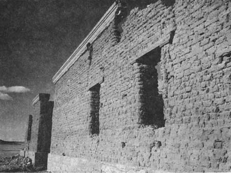
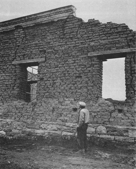
| FIGURE 65. Building 3-450 (left) and building (3-440), west walls and coping, before stabilization. Fort Union National Monument. |
|
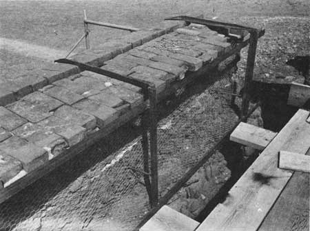
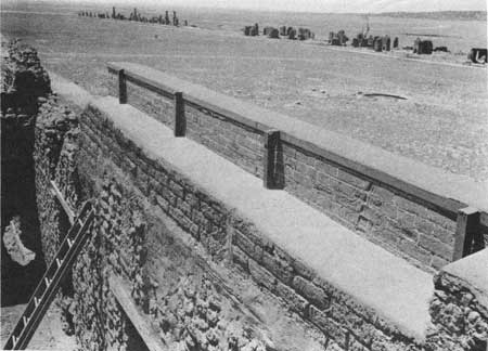
| FIGURE 66. Building 3-440, coping on west wall, during stabilization, Fort Union National Monument. |
|
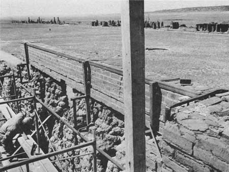
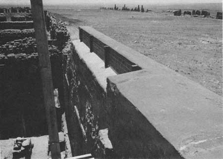
| FIGURE 67. Building 3-440, coping on west wall, during stabilization. Fort Union National Monument. |
|
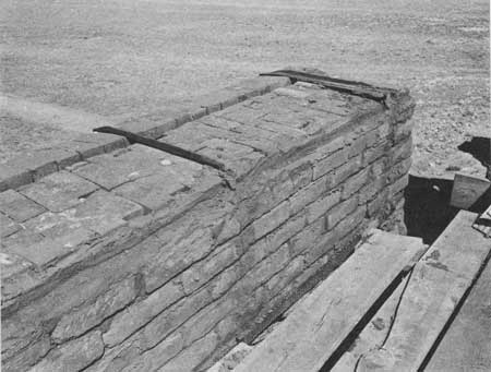
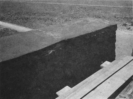
| FIGURE 68. Building 3-440, coping on west wall, during stabilization. Fort Union National Monument. |
|
| FIGURE 69. Building 3-440, west wall and coping, during stabilization. Fort Union National Monument. |
|
| FIGURE 70. Building 3-440, south half of coping on west wall, during stabilization. Fort Union National Monument. |

|
| FIGURE 71. Building 3-440, northwest wing wall, during stabilization. Fort Union National Monument. |
|
| FIGURE 72. Building 3-440, coping on west wall, after stabilization. Fort Union National Monument. |
|
| FIGURE 73. Building 3-440, coping on west wall, after stabilization. Fort Union National Monument. |

|
| FIGURE 74. Building 3-440, from the northeast, after stabilization. Fort Union National Monument. |
|
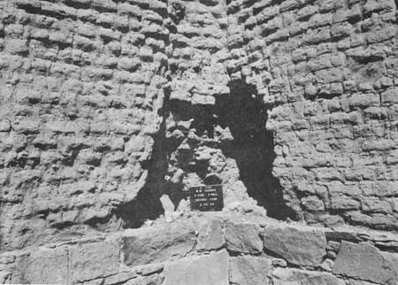
| FIGURE 75. Building 3-440, southwest corner, before stabilization. Fort Union National Monument. |
|
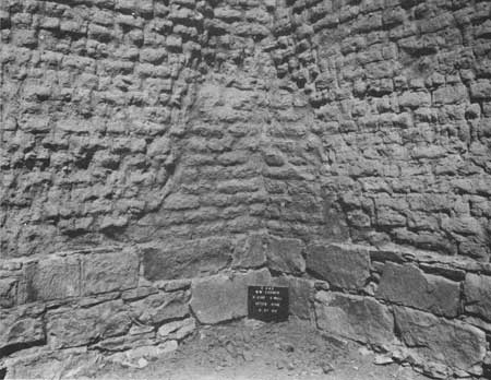
| FIGURE 76. Building 3-440, southwest corner, after stabilization. Fort Union National Monument. |
| <<< Previous | <<< Contents>>> | Next >>> |
archeology/10/app2b.htm
Last Updated: 16-Apr-2007