Last updated: January 24, 2018
Article
Monitoring Coastal Geologic Features and Processes
Department of Geosciences, University of West Georgia, 1601 Maple Street, Carrollton, Georgia 30118, USA
Rob Young
Program for the Study of Developed Shorelines, Western Carolina University, Cullowhee, North Carolina 28723, USA
Introduction
There is much informal or inconsistent terminology used to define or describe the coast. According to Oertel (2005), coast and coastline should be used when referring to the boundary between land and water at a regional scale; shore and shoreline are terms reserved for the same boundary but at a local scale. The area commonly referred to as the coastal zone is not strictly defined, but rather includes all land and water areas affected by marine processes. This may include areas many miles inland where even the weakest of tidal forces can be felt. In common usage, one tends to think of the beach as the primary or maybe only coastal environment. And the beach may be the most prominent, or most well known, of the coastal environments. The beach can be defined as an accumulation of sediment, moved by waves and currents.
The coastal environment, in a broad sense, is often considered to include anything landward of the shoreface, the water depth at which incoming waves begin to interact with the seafloor (Fig. 1). Such interaction begins when the water depth diminishes to one-half the wavelength on the incoming wave. That water depth marks the beginning of movement of sediment and is the dividing line between the offshore and the beach/dune system. The practical aspect of this demarcation is that it is the greatest depth from which waves are able to push sediment landward through the interaction of wave orbitals with the seafloor. Allen (1970) and Swift (1976) refer to this line as a “littoral energy fence” across which sediment from the landward side must move in order to be removed from the beach/dune system. A more practical limit for the water depth at which waves begin to impact on the sea bottom is one-quarter of a wavelength (Clifton and Dingler, 1984). Limits of terms inner shelf, mid-shelf, and outer shelf as used in this paper are shown. It is obvious that because wavelengths are so variable, usually an average is considered.
At an even larger scale, all earth-surface environments can be considered as either terrestrial (on land), transitional (transitional between land and water), or marine (under water). The transition zone between terrestrial and marine environments includes such environments as tidal flats, estuaries, dunes, and beaches and barrier islands. The focus of this chapter, then, is probably more correctly referred to as the transitional environment. The marine realm is covered in another chapter of this volume (Bush, this volume). Several terrestrial environments likewise are dealt with within their own chapters within this volume. Regardless, part of the beach system also belongs to the nearshore zone so it is impossible to completely disassociate the beach/transitional zone from the nearshore marine system. Standard beach terminology delineating the environmental zones of the nearshore system is shown in Figure 1.
The Encyclopedia of Coastal Science (Schwartz, 2005) is a lengthy (over 1200 pages) and expensive book, but it is comprehensive and contains a wealth of information on nearshore processes and sampling/monitoring techniques.

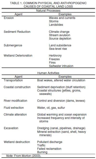
STRESSORS/POSSIBLE CHANGE TO THE COASTAL SYSTEM
The coastal system includes water, land, and air, and thus changes to the coastal system are a complex dynamic equilibrium of stimulus and response of those three spheres. That is, hydrodynamics of the nearshore marine system, substrate/land type and vegetation cover, plus the aeolian environment. The coast is subject to many different types of stressors including those natural and human induced (Table 1; Morton, 2003). The physical processes driving changes in the coastal system are fairly straightforward. These include waves, currents, and storm surges. The drivers of those forces include winter storms (known as extratropical cyclones), hurricanes (tropical cyclones), and possibly the effect of El Niño events. These forces act to modify sediment supply which ultimately changes the coastal geomorphology. Waves and currents may steepen unconsolidated shores forcing landslides and bluff retreat. Finally, there is a large-scale overprint of global sea-level rise and ground subsidence. Climate can also change over long enough time scales, which will exert control on coastal morphology and vegetation. Not to be understated is the role of human activities in land loss. Modifi cations of natural systems may include such things as transportation infrastructure, coastal construction, river modification, the extraction of hydrocarbon and groundwater, coastal excavation for beach replenishment, and stresses on wetlands.
Waves, currents, and seabottom composition (substrate) are also important aspects of energy flux in the water column. These, too, are addressed in the marine chapter. This chapter will focus on the shoreline (and shoreline change) and landward. The “Marine features and processes” chapter covers seaward from the shoreline/low-tide line. It is impossible to completely separate one system from the other, but for purposes of organization of this manual, we will do just that.
Thus, the “land-based” coastal features begin with the shoreline—the meeting place of water and land. Change in the position of any particular shoreline in the long term is controlled by sea level. The change in sea level in any given location is a function of what global sea level is doing and what the local/regional land surface is doing. Both can be changing, sometimes in the same direction, sometimes in opposite directions. See Douglas et al. (2001) for an overview of not only the physical driving forces of sea-level rise, but also the societal impacts. More than just the actual shoreline, other nearby features needing monitoring included the beach (shape and slope), dune line, bluff location and height, etc.
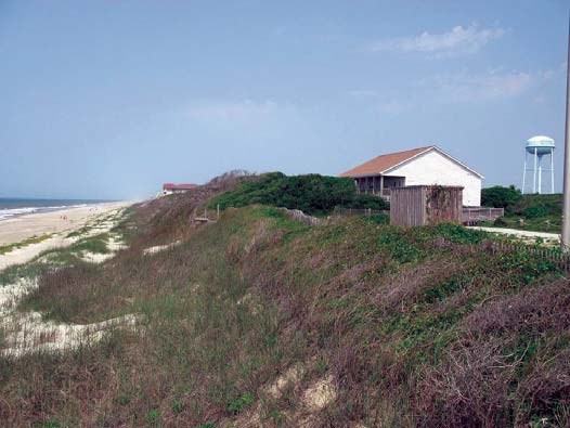
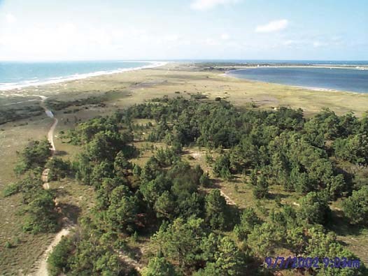
In general, the taller and thicker the vegetative growth, the more stable the site and the coastal geomorphic features. Maritime forests grow only at elevations high enough to preclude frequent overwash. In addition, because a mature maritime forest takes at least 100 years to develop, forested areas are generally the most stable. Major clearance of stable vegetation for development or by disease/fire greatly decreases the stability of coastal landforms.
Salt marshes—ecosystems that also flourish in quiet waters—often line the bay sides of islands, as well as the mainland margins of bays. The true salt marsh is a unique botanical environment because it consists of a single plant, Spartina. Marshes are important breeding grounds for many marine species and offer considerable protection from wave attack as well. Many salt marshes have been filled in for development, a practice that is now illegal. Areas around finger canals often have been built up with material dredged from the marsh to form the canal. Such sites have their own resulting problems. Buried marsh provides poor support for building foundations and does not provide a quality groundwater reservoir. Thus, such building sites typically have settling problems, an inadequate supply of fresh water, and septic systems that do not function properly. In addition, effluent waste from such sites has closed adjacent marshes to shellfishing. Marshes are very susceptible to flooding from even minor storms. New marsh can be planted on bay shorelines, and such replanting should be considered as an erosion buffer alternative to bulkheads and seawalls.
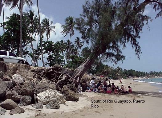
Wetland dynamics, especially during a rising sea level, are a critical part of the coastal system. Monitoring the landward or seaward movement of a wetland margin and the total acreage of a coastal wetland helps to manage and forecast changes that will influence flora and fauna and provides indicators of overall system vitality.
Just as barrier islands do, wetlands migrate landward with rising sea level. This occurs by drowning or eroding of the wetland on its ocean/estuary margin and formation of new wetland on its upland margin. Studies in Delaware Bay, for example, have shown that coastal wetlands were more extensive in the past than they are today (Allen, 1977). Numerous studies have examined the process and rate of vertical accretion in coastal wetlands (Reed, 1988; Stumpf, 1983; Richard, 1978; Harrison and Bloom, 1977). Many others have focused on the erosion or drowning of the seaward margin of coastal wetlands (Darienzo and Peterson, 1990; Hackney and Cleary, 1987; Orson et al., 1985; Hardisky and Klemas, 1983; and Rosen, 1978). These studies have shown that, as a general rule, vertical accretion in salt marshes is not keeping up with prevailing local relative sea-level rise. Furthermore, the aerial extent of these salt marshes has decreased over the last several decades. As stated earlier, coastal wetlands are dynamic environments and respond to sea-level rise by expanding on the upland margin. Yet, one can infer from this recent evidence of wetland loss that the rate of wetland transgression is not keeping up with the destruction of wetland on the seaward margin. This being the case, it is likely that further narrowing of our coastal wetlands can be expected under a regime of continuing, if not accelerating, sea-level rise (Fig. 5).

SELECTED METHODS FOR MONITORING COASTAL FEATURES AND PROCESSES
Monitoring vital signs of physical aspects of park ecosystems helps give insight not only into the general state of systems but also into changes in the systems or system vitality. The vital sign concept is very similar to the geoindicators approach to monitoring environments. The International Union of Geological Sciences (IUGS) defines geoindicators as “measures of surface or near-surface geological processes and phenomena that vary significantly over periods of less than 100 years and that provide information that is meaningful for environmental assessment” (Berger, 1996), and they are applied to a wide variety of environments (Berger, 1997). Geoindicators have a variety of management applications including environmental auditing and monitoring. Berger (1997) notes that the geoindicators approach identifies a minimum set of parameters that describe short-term environmental dynamics and that are proxies representing all the parameters on which processes depend.
Vital signs of coastal features and processes will be starting at the shoreline and moving landward. Table 2 summarizes the monitoring techniques discussed below. There is an infinite number of monitoring techniques and equipment available for monitoring the component environments of the coastal system. The following are selected in order to give a range of methods from low cost and low level of expertise needed, to high cost and higher level of expertise needed. Expertise needed may refer to either the expertise needed to use the equipment or to expertise needed to interpret the data, or both.

Definition. Change in position of any particular shoreline marker (beach, dune line, bluff, etc.).
Significance. Monitoring changes in the position of the shoreline or other shoreline markers indicates the dynamics between sea-level change, sediment supply, hydrography, and meteorology. The actual shoreline, the dividing line between land and the marine realm, is the most obvious. Perhaps no data is more critical for coastal management than shoreline change history.
Shoreline change data are critical in providing sound scientific basis for coastal management decisions including a baseline for setbacks, establishing long and short-term erosion rates, hazards and risk assessments, and coastal planning. In addition to creating a scientific basis for shoreline monitoring and management, shoreline change calculations will also provide useful data on the impacts of engineering structures on erosion, which is needed to fully understand the consequences that may surround emplacement of a specific type of structure. This information can be used to provide effective recommendations on management issues with minimal impacts to the environment. Therefore, it may be possible to devise shoreline management strategies and property damage mitigation plans that anticipate shoreline erosion due to sea-level rise and coastal storms.
Level 1: Geoindicator-Based Photo Monitoring
Equipment needed. Geoindicator checklists, camera, maps for location.
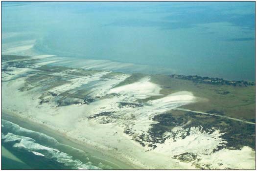
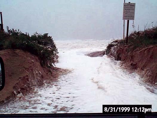
Complexity. Very simple.
Cost. Almost nothing; just printing photos and the cost of a camera if not in hand already.

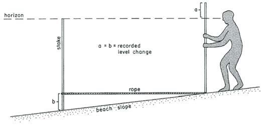
Equipment needed. Beach profile stakes, recording sheets.
Methodology. The simplest approach is the Emery method (Emery, 1961), also known as the “stake and horizon” method (Fig. 8). Two stakes are used in a profile perpendicular to the beach with sighting the horizon to determine whether the forward stake at higher or lower elevation than the backward stake. It takes two people on the stakes and one to record the measurements. It is decidedly low-tech, but gives very representative and reproducible results. A video available from the University of Maine Public Affairs Office (Kelley et al., 1999) gives an excellent demonstration of the methodology. A Global Positioning System (GPS) unit for precise locations will add accuracy to the studies. A limitation is the height of the people taking the surveys (Fig. 9). A small boat or skiff, if available, can be used to extend the profiles offshore some distance.
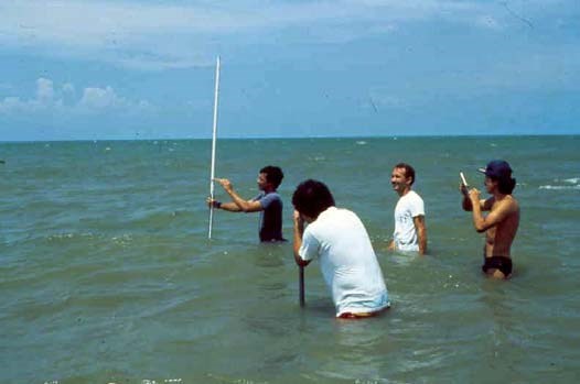

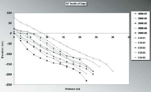
Timing. As with the geoindicator monitoring, profiling should be done as often as possible, at least yearly.
Complexity. Simple after a little training.
Cost. Very low; no specialized equipment is needed, and stakes can be made from scrap lumber.
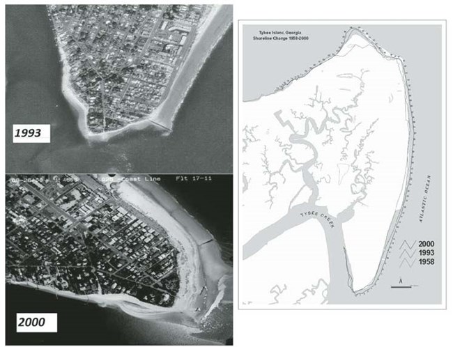
Air photo surveying is one of the best ways to monitor shoreline change. A series of several generations of shoreline position data, digitized off air photos, and analyzed in a geographic information system (GIS), can provide a wealth of data on shoreline behavior.
Equipment needed. A source for air photos. Typically photos can be obtained for a nominal cost from departments of transportation, the National Ocean Service, various state Departments of Natural Resources or equivalent agencies, the U.S. Department of Agriculture, and the U.S. Geological Survey.
Methodology. Shoreline change is doubtless very important, both for scientific understanding of the coastal system and for management. But there are limitations in mapping historical shoreline positions driven by limits of methodology accuracy, on data “quality,” and on our lack of understanding of the behavior of the system. Currently, shoreline mapping methods include point measurements (Stafford and Langfelder, 1971), photo enlargements (Dolan et al., 1980), the metric mapping system (Clow and Leatherman, 1984), digital shoreline detection (also known as raster scanning; Shoshany and Degani, 1992), and use of an analytical stereoplotter (American Society of Photogrammetry, 1980). Over the last two decades shoreline mapping has moved into the realm of the Digital Shoreline Mapping System (DSMS). The system provides digitizing routines for maps and aerial photographs and utilizes commonly available hardware/software such as electronic digitizers, UNIX-based computers, and GIS. The system calculates shoreline positions for maps and photographs and produces GIS- compatible output. Once the data are entered digitally and digital maps are produced, then the data can be analyzed digitally within a Digital Shoreline Analysis System (DSAS). DSAS reads the GIS-generated shoreline position data and, using extensive user specification such as choosing a reference baseline location and an alongshore sampling interval and cross-shore sampling tolerance, the system can calculate several measures of change simultaneously such as end-point rate (EPR; Fig. 13), average-of-rates (AOR), linear regression (LR), and jackknife (JK). The system produces reports on calculations for each transect and provides flexible output file format. DSAS systems are being continually upgraded by several researchers.

Bars reaching down from the zero line indicate that the dry beach was wider in front of the walled portion of the beach. Clearly, beaches in front of walls were narrower. It is thus argued that hard stabilization contributes to shoreline erosion.
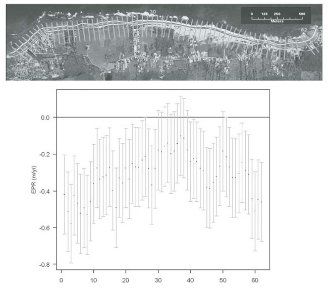
The horizontal axis is alongshore virtual transect numbers, the vertical axis is end point rate calculation shoreline change rate and error ranges from air photos. From Bush et al. (2007).
A major problem with an historical shoreline change study is determining the map accuracy and rate resolution. There can be horizontal RMS (root mean square) error for shoreline coordinates and error in the original data sources and converting the original sources (air photos or survey sheets) into historical shoreline position data. For example, in calculating the error in simple end-point rate calculations, imagine an error in oldest shoreline position of 9.25 m and an error in most recent shoreline position also of 9.25 m, giving a total error of 18.50 m. The longer the period of study (years between oldest and newest shoreline position data source), the less the error per year. For example, in the above calculation, if the number of years between the two shorelines is 36 years, the average error per year is on the order of 0.51 m/yr, an acceptable error.
But what do the data really tell us? That is, do the data answer important geologic questions such as: do the data reflect the real long-term trend? How many data points do we have? Are there storm influences or seasonal changes? Do decadal or climatic variations play a role? Are there wind-, wave-, or tide-influenced fluctuations? We may never know the pre-photo events affecting the area of study. Moreover, what are we really measuring? That is, which is the best shoreline indicator? Most surveys now use the wet/dry (mean high water or MHW) line. Some, however, use a vegetation line, bluff line or cliff line. Which is most stable? Which is more reproducible?
Complexity. Very complex; highly skilled personnel is needed for data entry and analyses of shoreline position data.
Cost. High, depending on cost of air photos. A GIS computer work station is needed. The computer equipment and even the expertise may be available at nearby universities.
Vital Sign 2: Coastal Dune Geomorphology
Definition. Monitoring the nature of coastal dunes (presence/absence, dune volume/elevation, dune position)
Significance. Coastal dunes provide a measure of protection for the land against forces of the sea including storm waves and surges. A study of the impacts of Hurricane Hugo (1989) in South Carolina revealed that buildings behind large dunes suffered little damage during the storm (Thieler and Young, 1991).
Level 1: Geoindicator-Based Photo Monitoring
See the description for Vital Sign 1, Level 1, above, using the geoindicator approach.
Level 2: Repeat Ground Surveys
The same approach as presented for Vital Sign 1, Level 2, can be employed by expanding the methodology inland and measuring individual dunes or other features (Fig. 15).

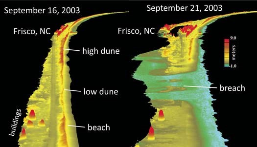
Equipment needed. Very specialized, high-technology equipment, typically available only through governmental agencies. There must be partnering with other agencies for application of light detection and ranging (LIDAR) methodology. The USGS maintains a LIDAR Web site (http://lidar.cr.usgs.gov/) called CLICK. It is the USGS Center for LIDAR Information Coordination and Knowledge. See also NOAA’s coastal remote sensing Web site at http://www.csc.noaa.gov/crs/rs_apps/sensors/lidar.htm.
Methodology. LIDAR is a remote sensing system used to collect topographic data. Lasers are used from aircraft to measure in great detail variations in the vertical dimension. Precisions on the order of 15 cm are possible. Repeat surveys can be used to detect shoreline changes, including volumetric changes (Fig. 16). See the CLICK site or NOAA’s http://www.csc.noaa.gov/products/sccoasts/html/tutlid.htm for further information.
Timing. Owing to the cost of data collection and time and cost involved in data analysis, LIDAR data are likely going to be sparse for many areas. Areas along, for example, the Gulf of Mexico coast, however, have had repeat surveys because of frequent hurricane impacts.
Complexity. Highly complex.
Cost. High.
Vital Sign 3: Coastal Vegetation Cover
Definition. The degree and nature of the vegetation cover in the immediate coastal zone.
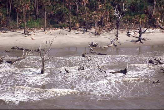
Vegetation cover also is important in evaluating the hydrologic system of the area of study (Fig. 18). Existing, older, landuse maps are outdated and generalized, so often new land-use classification gives an accurate picture of current development trends. Land-use classification goes beyond vegetation cover to include all other types of land cover such as developed areas (roof tops, paved expanses, etc.) waterways, agricultural lands, and so forth.

See the description for Vital Sign 1, Level 1, above, using the geoindicator approach, concentrating on the vegetation. Vegetation classes to include will depend on local environment.
Level 2: Ground Surveys with Vegetation Classification
Equipment needed. A more thorough evaluation than Level 1 only in means of adding much more complete surveys of vegetation cover instead of evaluating selected sites as in the geoindicators approach.
Methodology. Involves driving, walking, using an all-terrain vehicle, etc., over study area to map vegetation cover from site inspection covering the area in as much detail as possible.
Timing. Yearly surveys would be ideal, but are not critical. However, if there are areas observed to be undergoing rapid change because of natural or human impacts, more frequent surveying is warranted.
Complexity. Low complexity, but labor intensive.
Cost. Low to moderate cost. Transportation, photography, and maps are the greatest expense.
Level 3: Repeat Aerial Photography, or Satellite Images
Equipment needed. Air photos as discussed for shoreline change, above, are needed. Color photographs are much more useful for vegetation cover mapping while black and white will suffice for shoreline change detection. Black and white photographs are of some use for vegetation cover, but color is much better. For both air photo and for satellite imagery evaluation, specialized geospatial analysis computer equipment, software, and expertise are needed.
Methodology. Digitizing air photos, and manipulating air photos and satellites imagery, is done within GIS and remotesensing computer work stations. Ideally, computer results would be field checked for ground truthing of results. Only an abbreviated methodology is given here because the work is so highly specialized that the person or persons actually performing the investigation will be well versed. In general, though, air photos would require hand digitizing of different vegetation cover types, whereas the satellite imagery can be analyzed digitally based on the various electromagnetic wavelengths reflected by different plants and other land cover types.
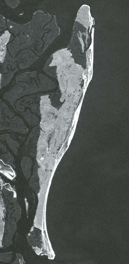
See the Web site of the USGS Land Cover Institute at http://landcover.usgs.gov/ for more information.
Timing. As new satellite imagery or air photos becomeavailable.
Complexity. Very complex. Must be done by experts. Partnering with a university or federal agency is probably a must.
Cost. A main cost can be the satellite imagery, assuming the computer equipment and software is already available.
Definition. Cross-shore elevation allowing for a determination of coastal geomorphology and sediment volumes.
Significance. Topographic changes of coastal landforms are a reflection of the dynamics between processes of air, water, and land. A standard geomorphology concept is that, in general, the larger the feature, the more persistent it is. That is, the more slowly it changes. Thus, smaller features such as dunes will change much more quickly and dramatically than larger features such as interior beach ridges. Therefore, the type of monitoring and the frequency of monitoring will depend, in part, on the feature to be monitored.
Level 1: Repeat Photography
The approach is not too different than those given using air photos in previous sections. The only difference is the feature to be monitored: shoreline position in the case of Vital Sign 1 and vegetation type and expanse in the case of Vital Sign 3. In this case, coastal landforms are the target of interest on the air photos. Other than that, all descriptions given above hold true for this case.
Level 2: GPS or Traditional Survey
Equipment needed. A GPS receiver or hand surveying tools.
Methodology. A GPS survey means driving or walking around a feature making several recordings of position using a handheld GPS receiver. The more frequently position data are recorded, the more precisely a feature can be recorded and monitored. The horizontal dimensions are very accurate (within a meter or so) with a good GPS system. Vertical dimensions may not be quite as accurate, but accuracy can be improved by employing higher quality equipment or by tying GPS readings into an elevation benchmark or to a traditional survey. A traditional survey entails hand surveying. This involves many detailed measurements from known locations. It is very accurate, but very time consuming.
Timing. Depends on the dynamics of the feature or features to be monitored.
Complexity. Moderate.
Cost. Moderate, depending on the GPS unit. If surveying by hand, personnel costs will be very high.
Level 3: LIDAR
See discussion of LIDAR, above.
Vital Sign 5: Composition of Beach Material
Definition. Description of the sediment or other material making up the beach, dunes, bluff, or intertidal zone.
Significance. The composition of the material comprising the area of study gives great detail about the geologic history including human impacts in many cases. Obviously, a rock cliff at the coast will behave much differently than a sandy bluff during an individual storm as well as over longer time frames. Dominance of shell material means a marine source for much of the sediment. Pure quartz indicates an area not only away from marine influence but also sediment that has been reworked many times so that other, less-resistant, material has eroded away.
Level 1: Repeat Photography with Field Notes
Equipment needed. A camera, field notebook, and GPS for positioning.
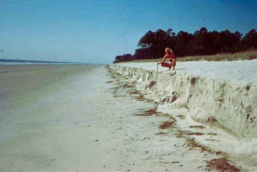
Timing. Yearly at least.
Complexity. Low complexity.
Cost. Low.
Equipment needed. Sampling devices, sample storage containers.
Methodology. Sampling on land can be as simple as spooning some sediment into a plastic bag. The Encyclopedia of Coastal Science (Schwartz, 2005) is a lengthy (over 1200 pages) and expensive book, but it is comprehensive and contains a wealth of information on nearshore processes and sampling/monitoring techniques. Description of the samples must be done using standard methodologies such as those described by Lewis and McConchie (1994) or Sukhtankar (2008).
Timing. Yearly should suffice.
Complexity. It is not overly complex, but training is needed.
Cost. Moderate.
Level 3: Detailed Sedimentological Description
Equipment needed. In addition to the equipment needed to obtain samples, analysis can be very complex and costly. It would be advantageous to develop a working relationship with a nearby university or USGS laboratory for help in sedimentological descriptions.
Methodology. Analysis of samples is an entirely separate issue from obtaining the samples. Depending on facilities everything from simple textural analyses (grain size and sorting) to composition (identifi cation of grains) to organic carbon content, and even radiometric age dating is possible. The USGS has loads of information on sedimentologic techniques. See, for example, USGS (2000) as an example of techniques for grain size analysis and data handling.
Timing. Yearly at most.
Complexity. Very complex, particularly in the nuances of sedimentary structures and microstratigraphy.
Cost. Can be very high if sophisticated techniques are required.
Vital Sign 6: Coastal Wetland Position and Acreage
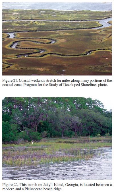
Significance. Coastal marshes (Figs. 21 and 22) play a critical role in sustaining the health of coastal ecosystems. They are centers of biological productivity important for active fisheries. They may act as a buffer between the marine and freshwater environments, filtering out contaminants from the uplands. They are pathways of migration for numerous species of waterfowl (the availability of wetlands is important in maintaining species diversity). It is clear that preserving and properly managing this nation’s coastal wetlands will directly or indirectly benefit us all. It is imperative that any agency charged with managing large portions of coastal wetlands understand the dynamics of these environments. Protecting coastal wetlands in a period of continued, and possibly accelerating, sea-level rise may require flexible management techniques that have yet to be considered.
A necessary first step is simply to monitor the size and location of identified wetlands. The techniques will not differ much from those previously discussed.
Level 1: Simple Surveys
Equipment needed. GPS units and record keeping materials.
Methodology. Identify the boundaries of the wetland in question. Take as many position readings as possible using hand held GPS units. Post data on a map. Each generation of maps could ultimately be digitized for easy comparison with future maps using computer graphics. That is not necessary, however, as hand comparison is worthwhile as well.
Timing. Probably once every several years is enough unless there is some kind of disturbance, human-induced or natural, that bears watching.
Complexity. Not complex; need knowledge of working with GPS units and plotting data on a map.
Cost. Low cost.
Level 2: Repeat Aerial Photography
The approach is not too different than those given using air photos in previous sections. The only difference is the feature to be monitored. In this case, coastal marshes and wetlands are the target of interest on the air photos. Other than that, all descriptions given above hold true for this case. In fact, considering wetland vegetation, this could be considered as part of the vegetation monitoring program.
Level 3: Satellite Interpretation
Same as for vegetation monitoring only concentrating on wetlands.
Vital Sign 7: Coastal Wetland Accretion
Definition. The rate of sediment accumulation in a coastal wetland.
Significance. Sediment accumulation in coastal wetlands is critical for the land surface to keep pace with sea-level rise. Otherwise, the wetlands would become inundated. Inherent in that, is that as the surface of the marsh rises, the organic material trapped within the sediments may account for a large amount of carbon locked out of the atmospheric system. Much effort has been directed at understanding carbon accumulation, cycling, and long-term storage in wetlands. Studies have ranged from site-specific determinations of soil organic matter accumulation (e.g., Craft et al., 1993) to region-wide accumulation (e.g., Botch et al., 1995), and ultimately, global assessments of the total carbon mass stored in wetland soils during the Holocene (Moore and Bellamy, 1974). Much recent interest has focused on changes in wetland carbon reservoirs during historical times—primarily human induced. Armentano and Menges (1986) estimate changes in carbon flux and loss of carbon storage capacity for temperate zone organic soils due to wetland drainage and similar disturbances. They found that the wetlands in some regions of the world (e.g., central Europe) are presently carbon sources rather than sinks due to agricultural drainage, forestry operations, and peat burning.
Level 1: Sediment Traps
Equipment needed. Field sediment traps.
Methodology. This is a highly sophisticated sampling technique, necessarily so because of the sensitivity of the data. Accumulation rates are often very low, so high precision is a must. See Mudroch and MacKnight (1994) for sampling methodology and Leonard et al. (2002) for an example application of sediment trap methodology in estuaries. Large sediment traps might be necessary in some instances as in the nearshore or lake environments. See Honjo and Doherty (1988) for an example.
Timing. Seasonal if possible, and during events.
Complexity. Will need a high level of expertise for deploying sediment traps and retrieving and analyzing the data.
Cost. Moderate for cost of traps and field work.
Level 2: Cryogenic Coring
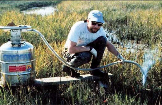
Methodology. Cryogenic coring is a highly specialized undertaking. See the USGS Web page http://www.pwrc.usgs.gov/set/readMarkers.html for an example of the technique.
Timing. Yearly at the most.
Complexity. Highly detailed sampling techniques means this is best left to the experts.
Cost. Moderate.
Equipment needed. To investigate historical rates of wetland accretion means having to bring in the third and fourth dimensions. Highly precise spatial data are needed, and absolute dating methods must be employed. This is necessarily equipment and labor intensive.
Methodology. Each site to be studied will be covered with several vibracore transects extending from the upland across the transition zone into the marsh. Vibracores (after the methods of Lanesky et al., 1979) can be supplemented with one-inch diameter, hand-auger cores. The hand-auger will be used to fill in any gaps in resolution not provided by the vibracores (e.g., detailed mapping of the transgressed upland surface). The vibracore tops will be surveyed in using differential GPS providing the detail necessary to examine the elevation of the transgressed upland surface in the cores. This kind of detail is important for determining accurately the slope of this surface and the rate of transgression of the marsh edge.
Vibracores must be taken to a lab where they can be split, photographed, and sampled at ~10 cm intervals downcore. The boundary between the submerged upland and the base of the salt marsh must be identified and the basal marsh sediments (this is the leading edge of the transgressing marsh) sampled for radiocarbon dating. Depending on available funds, the more radiocarbon dates the better. A hand-auger core should also be recovered at each vibracore location for possible 137Cs and 210Pb sequences to determine if accretion rates vary across the transition zone and from site to site.
The modern surface sediments in each site should be sampled and analyzed using standard sedimentological techniques—grain size analysis by settling tube (Theide et al., 1976) and percent loss on ignition as a proxy for plant organic content (Davies, 1974). These characteristics can then be mapped as a sediment facies map. The modern vegetational assemblages should be mapped in detail using a standard line/interval method listing the species dominance hierarchy at each sediment sample site. These maps will provide the baseline data set for the modern biogeological relationships at each site. Similar procedures should be carried out for the sediments at 10 cm intervals in the vibracores in order to determine if the sedimentology, vegetation, or the relationships between the two have changed during marsh transgression.
Analysis of the marsh flora in the cores must be carried out using, for example, the methods of Allen (1977). It is important to determine whether these coastal marshes are transgressing as stable vegetational communities or whether they are changing as they migrate.
The results of such a study can include profi les, topographic contour maps, sediment isopach maps, and sediment facies maps. Ultimately, a series of maps for each study area can be produced predicting areas of new wetland formation and floral succession during the next 50, 100, 250, and 1000 years, assuming minimum, moderate, and maximum sea-level rise scenarios. Predictions will be based on the determined rate of wetland transgression at each transect adjusted for any changes in the bordering upland slope or environment. Notations on the maps will indicate areas where human activity may interfere with or prevent the formation of new wetland. This is the ultimate in long-term management of the system.
Timing. Probably will be done once only.
Complexity. Exceedingly complex.
Cost. Very expensive.
CASE STUDY—CUMBERLAND ISLAND, GEORGIA
The Georgia coast extends ~150 km. Only four barrier islands are accessible by car (Tybee, St. Simons, Sea Island, and Jekyll), and are heavily developed.
A two-part approach to evaluating coastal hazards was developed to aid coastal planning and management decisions for Cumberland Island National Seashore (Barrett et al., 2003). The goal was to provide guidelines for environmental assessment of a shoreline and to serve as an evaluative tool for examining natural hazard risk, to aid in developing management strategies. The first component of the plan is a field-based program of observations and documentation. This involves (1) a simple geoindicators checklist of several hazards-related parameters including descriptions of the general setting, shoreline state, nearshore setting, and onshore setting; (2) beach profiling using a simple stake and horizon method; (3) a set of photographs to document the setting; and (4) recording site locations using a handheld GPS unit.
The second component of the plan is a computer-assisted analysis utilizing remote sensing and GIS technology. This involves (1) land use/land cover from satellite imagery; (2) shoreline change analysis from air photos and NOAA T-sheets; (3) evaluation of historical beach profiles (if and when available); (4) creating and managing a database; and (5) creating and maintaining a Web site for maximum distribution of findings.
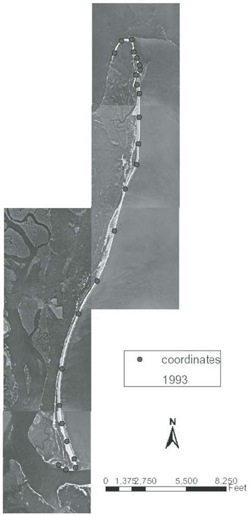
Field sites were selected based on field inspection, anecdotal evidence of interesting erosion patterns, or any number of reasons suggesting that the site is deemed worthy of monitoring. For each selected field sites (Fig. 24), field description was made along with completion of a geoindicators checklist (Table 3), beach profiling using the Emery (1961) method discussed earlier (Figs. 8 and 9), and photo documentation. Each site’s photographs, geoindicators checklist, beach profile plots, and any other information are organized into a 3-ring binder. Stakeholders were encouraged to visit each site at least once a year, or more frequently in the case of passage of a large storm.
Phase Two: Digital Applications
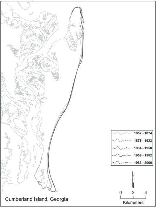
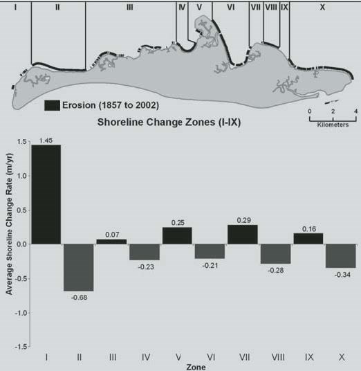
Land cover change was assessed using satellite imagery (Fig. 19). Shoreline change analysis from T-sheets and aerial photography was done (Fig. 25). See also Jackson (2006), Jackson et al. (2007), and Langley et al. (2003) for methodology. Historical beach profiles were not available, but should be acquired if possible. Shoreline change was calculated using end point rate method. That is, the difference between the oldest and youngest years’ shoreline position data available divided by the number of intervening years. Shoreline changes of the estuarine shoreline of Cumberland Island (Jackson et al., 2007) are shown in Figure 26.
Field inspections of several sites on Cumberland Island National Seashore showed that, at least for the sites visited, there are no major coastal hazards present on this undeveloped island. Shoreline change analysis from air photos confirmed this observation. A flow chart was developed to provide an easy to follow guide to initiating and continuing the proposed coastal evaluation technique (Fig. 27). The beauty of this approach is that the field observation component is very inexpensive and can still provide enough information on which to base management decisions. The digital component is not strictly necessary, but can be used to complement the field observations if and when resources are available. A byproduct of such a study is that the amount of data generated must be kept organized and accessible. As such, creating and managing a database and Web site is critical.
CONCLUSIONS
Additional aspects of the coastal zone that may be of interest include the following.
Meteorology and Oceanography:
• Storm frequency
• Wind speed and direction
• Local wave data
• Rate of local relative sea level rise
• Nearshore bathymetry
• Location of nearshore hardgrounds
Other:
• Land use change in coastal watershed
• Location of coastal engineering structures
• Beach replenishment history
• Degree of alteration of coastal wetlands
• Location of former inlets on barrier islands


REFERENCES CITED
Alexander, C.R., Bush, D.M., Foyle, A.M., Langley, S.K., Henry, V.J., and Jackson, C., 2001, An integrated GIS-based approach to quantifying the rates of shoreline change in the Georgia bight: A progress report: Geological Society of America Abstracts with Programs, v. 33, no. 6, p. A-103
Allen, E.A., 1977, Petrology and stratigraphy of Holocene coastal-marsh deposits along the western shore of Delaware Bay: Newark, Delaware, Delaware Sea Grant College Program, DEL-SG-20-77, 287 p.
Allen, J.R.L., 1970, Physical Processes of Sedimentation: London, Unwin, 248 p.
American Society of Photogrammetry, 1980, Manual of Photogrammetry, Chester C. Slama, ed.: Falls Church, Virginia, American Society of Photogrammetry, 4th edition.
Anders, F.J., and Byrnes, M.R., 1991, Accuracy of shoreline change rates as determined from maps and aerial photographs: Shore and Beach, v. 59, no. 1, p. 17–26.
Armentano, T.V., and Menges, E.S., 1986, Patterns of change in the carbon balance of organic soil-wetlands of the temperate zone: Journal of Ecology, v. 74, p. 755–774, doi: 10.2307/2260396.
Barrett, S.R., Boothe, T.A., Bush, D.M., Young, R.S., Neal, W.J., and Jackson, C.W., 2003, A Two-phase Coastal Evaluation Plan for Hazard Risk Assessments, an Example from Cumberland Island, Georgia: Geological Society of America Abstracts with Programs, v. 35, no. 6, p. 491.
Berger, A.R., 1996, The geoindicator concept and its application: an introduction, in Berger, A.R., and Iams, W.J., eds., Geoindicators: assessing rapid environmental changes in earth systems: Rotterdam, A.A. Balkema, p. 1–14.
Berger, A.R., 1997, Assessing rapid environmental changes using geoindicators: Environmental Geology, v. 32, no. 1, p. 36–44, doi: 10.1007/s002540050191.
Botch, M.S., Kobak, K.I., Vinson, T.S., and Kolchugina, T.P., 1995, Carbon pools and accumulation in peatlands of the former Soviet Union: Global Biogeochemical Cycles, v. 9, p. 37–46, doi: 10.1029/94GB03156.
Bush, D.M., 2009, this volume, Marine features and processes, in Young, R., and Norby, L., Geological Monitoring: Boulder, Colorado, Geological Society of America, doi: 10.1130/2009.monitoring(07).
Bush, D.M., Neal, W.J., Young, R.S., and Pilkey, O.H., 1999, Utilization of Geoindicators for Rapid Assessment of Coastal-hazard Risk and Mitigation: Ocean and Coastal Management, v. 42, no. 8, p. 647–670, doi: 10.1016/S0964-5691(99)00027-7.
Bush, D.M., Wilson, C.G., Gibson, J.C., Langley, S.K., Alexander, C.R., Henry, V.J., and Jackson, C.W., 2003, Quantitative Shoreline Change Analysis of the Georgia Coast from Aerial Photography and T-Sheets, NOAA Southeastern Coastal Ocean Science Meeting, Charleston, South Carolina, January 27–29, 2003.
Bush, D.M., Neal, W.J., and Jackson, C.W., Jr., 2007, Puerto Rico’s vulnerable coastal communities: Risk, mitigation, management: Geological Society of America Abstracts with Programs, v. 39, no. 6, p. 241.
Cahoon, D.R., Lynch, J.C., and Knaus, R.M., 1996, Improved cryogenic coring device for sampling wetland soils: Journal of Sedimentary Research, v. 66, p. 1025–1027.
Clifton, H.E., and Dingler, J.R., 1984, Wave-formed structures and paleoenvironmental reconstruction: Marine Geology, v. 60, p. 165–198, doi: 10.1016/0025-3227(84)90149-X.
Clow, J.B., and Leatherman, S.P., 1984, Metric mapping: An automated technique of shoreline mapping, in Proceedings, 44th American Congress on Surveying and Mapping: Falls Church, Virginia, American Society of Photogrammetry, p. 309–318.
Cowardin, L.M., Carter, V., Golet, F.C., and LaRoe, E.T., 1979, Classification of wetlands and deepwater habitats of the United States: Washington, D.C., U.S. Department of the Interior, Fish and Wildlife Service, Office of Biological Services, FWS/OBS-79/31, 142 p. Reprinted in 1992.
Craft, C.B., Seneca, E.D., and Broome, S.W., 1993, Vertical accretion in microtidal regularly and irregularly flooded estuarine marshes: Estuarine, Coastal and Shelf Science, v. 37, p. 371–386, doi: 10.1006/ ecss.1993.1062.
Crowell, M., Leatherman, S.P., and Buckley, M.K., 1991, Historical Shoreline Change: Error Analysis and Mapping Accuracy: Journal of Coastal Research, v. 7, no. 3, p. 839–853.
Danforth, W.W., and Thieler, E.R., 1992a, Digital Shoreline Mapping System (DSMS) User’s Guide, Version 1.0: Reston, Virginia, U.S. Geological Survey Open-File Report No. 92-240, 33 p.
Danforth, W.W., and Thieler, E.R., 1992b, Digital Shoreline Analysis System (DSAS) User’s Guide, Version 1.0: Reston, Virginia, U.S. Geological Survey Open-File Report No. 92-355, 42 p.
Darienzo, M.E., and Peterson, C.D., 1990, Episodic tectonic subsidence of Late Holocene salt marshes, Northern Oregon Central Cascadia Margin: Tectonics, v. 9, no. 1, p. 1–22, doi: 10.1029/TC009i001p00001.
Davies, B.E., 1974, Loss-on-ignition as an estimate of soil organic matter: Soil Science Society of America Proceedings, v. 38, p. 150–151.
Dolan, R., Hayden, B.P., May, P., and May, S., 1980, The reliability of shoreline change measurements from aerial photographs: Shore and Beach, v. 48, no. 4, p. 22–29.
Douglas, B.C., Kearney, M.S., and Leatherman, S.P., 2001, Sea Level Rise: History and Consequences: Academic Press, 232 p.
Douglas, B.C., and Crowell, M., 2000, Long-term Shoreline Position Prediction and Error Propagation: Journal of Coastal Research, v. 16, no. 1, p. 145–152.
Emery, K.O., 1961, A simple method of measuring beach profiles: Limnology and Oceanography, v. 6, p. 90–93.
FEMA, 2000, Coastal Construction Manual: Washington, D.C., Federal Emergency Management Agency, Mitigation Directorate, FEMA 55CD, Third Edition.
Hackney, C.T., and Cleary, W.J., 1987, Saltmarsh loss in southeastern North Carolina lagoons: Importance of sea level rise and inlet dredging: Journal of Coastal Research, v. 3, no. 1, p. 93–97.
Hardisky, M.A., and Klemas, V., 1983, Tidal wetlands natural and manmade changes from 1973–1979 in Delaware: Mapping techniques and results: Environmental Management, v. 7, no. 4, p. 339–344, doi: 10.1007/BF01866916.
Harrison, E.Z., and Bloom, A.L., 1977, Sedimentation rates on tidal salt marshes in Connecticut: Journal of Sedimentary Petrology, v. 47, no. 4, p. 1484–1490.
Honjo, S., and Doherty, K.W., 1988, Large aperture sediment traps: Deep-Sea Research, v. 35, no. 1, p. 133–149, doi: 10.1016/0198-0149(88)90062-3.
Jackson, C.W., Jr., 2006, Historical Back-Barrier Shoreline Changes Along Cumberland Island, Georgia, 1857–2002, Unpublished report to the National Park Service, 92 p.
Jackson, C.W., Jr., Alexander, C., and Bush, D.M., 2007, Back-Barrier Shoreline Change History: Cumberland Island, Georgia, 1857–2002: Southeastern Geology, v. 45, no. 2, p. 73–85.
Kelley, J.T., Belknap, D.F., and Dickson, S.D., 1999, Measuring the Shape of a Beach: a beach profiling training video: University of Maine Public Affairs Office, R. Winter, video production, Val Williams, cover design, 25 min.
Knaus, R.M., 1986, A cryogenic coring device for sampling loose, unconsolidated sediments near the water-sediment interface: Journal of Sedimentary Petrology, v. 56, p. 551–553.
Knaus, R.M., and Cahoon, D.R., 1990, Improved cryogenic coring device for measuring soil accretion and bulk density: Journal of Sedimentary Petrology, v. 60, p. 622–623.
Lanesky, D.E., Logan, B.W., Brown, R.G., and Hine, A.C., 1979, A new approach to portable vibracoring underwater and on land: Journal of Sedimentary Petrology, v. 49, p. 654–657.
Langley, S.K., Alexander, C.R., Bush, D.M., and Jackson, C.W., 2003, Modernizing shoreline change analysis in Georgia using topographic survey sheets in a GIS environment, in Byrnes, M.R., Crowell, M., and Fowler, C., eds., Shoreline Mapping and Change Analysis: Technical Considerations and Management Implications: Journal of Coastal Research Special Issue 38, p. 168–177.
Leonard, L.A., Wren, P.A., and Beavers, R.L., 2002, Flow dynamics and sedimentation in Spartina alternifl ora and Phragmites australis marshes of the Chesapeake Bay: Wetlands, v. 22, no. 2, p. 415–424.
Lewis, D.W., and McConchie, D.M., 1994, Practical Sedimentology, Springer; 2nd edition, 213 p.
Moore, L.J., 2000, Shoreline mapping techniques: Journal of Coastal Research, v. 16, no. 1, p. 111–124.
Moore, P.D., and Bellamy, D.J., 1974, Peatlands: London, Elek Science, 221 p.
Morton, R.A., 2003, An Overview of Coastal Land Loss: With Emphasis on the Southeastern United States: U.S. Geological Survey, Open File Report 03-337, 29 p.
Mudroch, A., and MacKnight, S., 1994, Handbook of Techniques for Aquatic Sediments Sampling: CRC Press, 236 p. Nordstrom, K., Psuty, N., and Carter, B., eds., 1990, Coastal dunes: Form and process: Chichester, Wiley, 392 p.
Oertel, G.F., 2005, Coasts, Coastlines, Shores, and Shorelines, in, Schwartz, M.L., ed., Encyclopedia of Coastal Science, Springer, p. 323–327.
Orson, R., Panagetou, W., and Leatherman, S.P., 1985, Response of tidal salt marshes of the United States Atlantic and Gulf Coasts to rising sea levels: Journal of Coastal Research, v. 1, no. 1, p. 29–37.
Reed, D.J., 1988, Sediment dynamics and deposition in a retreating coastal salt marsh: Estuarine, Coastal and Shelf Science, v. 26, p. 67–79, doi: 10.1016/0272-7714(88)90012-1.
Richard, G.A., 1978, Seasonal and environmental variations in sediment accretion in a Long Island salt marsh: Estuaries, v. 1, no. 1, p. 29–35, doi: 10.2307/1351647.
Rosen, P.S., 1978, A regional test of the Bruun Rule on shoreline erosion: Marine Geology, v. 26, p. M7, doi: 10.1016/0025-3227(78)90052-X.
Schwartz, M.L., ed., 2005, Encyclopedia of Coastal Science: Springer, 1211 p.
Shoshany, M., and Degani, A., 1992, Shoreline detection by digital image processing of aerial photography: Journal of Coastal Research, v. 8, no. 1, p. 29–34.
Stafford, D.B., and Langfelder, J., 1971, Air photo survey of coastal erosion: Photogrammetric Engineering, v. 37, p. 565–575.
Stumpf, R.P., 1983, The process of sedimentation on the surface of a salt marsh: Estuarine, Coastal and Shelf Science, v. 17, no. 5, p. 495–508, doi: 10.1016/0272-7714(83)90002-1.
Sukhtankar, R.K., 2008, Applied Sedimentology: CBS Publishers & Distributors, 170 p.
Swift, D.J.P., 1976, Continental shelf sedimentation, in Stanley, D.J., and Swift, D.J.P., eds., Marine sediment transport and environmental management: New York, John Wiley, p. 311–350.
Theide, J., Chris, T., Clauson, M., and Swift S.A., 1976, Settling tubes for size analysis of fine and coarse fractions of oceanic sediments: Oregon State University, College of Oceanography, Ref. 76-78.
Thieler, R.E., and Danforth, W.W., 1994a, Historical shoreline mapping (I): improving techniques and reducing position errors: Journal of Coastal Research, v. 10, no. 3, p. 549–563.
Thieler, R.E., and Danforth, W.W., 1994b, Historical shoreline mapping (II): application of the Digital Shoreline Mapping and Analysis Systems (DSMS/DSAS) to shoreline change mapping in Puerto Rico: Journal of Coastal Research, v. 10, no. 3, p. 600–620.
Thieler, R.E., and Young, R.S., 1991, Impact of Hurricane Hugo; September 10–20, 1989, in, Finkl, C.W., ed., Journal of Coastal Research, Special Issue 8, p. 187–200.
USGS, 2000, USGS East-Coast sediment analysis: procedures, database, and georeferenced displays: U.S. Geological Survey Open-File Report 00-358, http://pubs.usgs.gov/of/of00-358/ [accessed 29 January 2009].
Wright, E.E., 1989, The effect of hard stabilization on the sediment transport system along the shoreline of Puerto Rico [unpublished master’s thesis]: Durham, North Carolina, Duke University, 200 p.
BIBLIOGRAPHY AND RECOMMENDED READING
Beatley, T., Brower, D.J., and Schwab, A.K., 2002, An Introduction to Coastal Zone Management, (2nd Edition): Island Press, 329 p. (A comprehensive overview of coastal planning and management issues for students and professionals.)
Bird, E.C.F., 1984, Coasts: An Introduction to Coastal Geomorphology, (3rd Edition): Basil Blackwell, Inc., 320 p. (An introductory textbook on coastal geomorphology from worldwide examples, looking at the human and natural processes.)
Carter, R.W.G., 1988, Coastal Environments: An Introduction to the Physical, Ecological and Cultural Systems of Coastlines: Academic Press, 617 p. (An excellent text for almost all aspects of the coastal zone, although management of coastal environments is its emphasis.)
Carter, R.W.G., and Woodroffe, C.D., 1994, Coastal Evolution: Late Quaternary Shoreline Morphodynamics: Cambridge University Press, 517 p. (Quite involved and lengthy, but covers all aspects of nearshore and coastal systems. For the advanced user.)
Cicin-Sain, B., and Knecht, R.W., 1998, Integrated Coastal and Ocean Management: Concepts and Practices: Island Press, 517 p. (An analysis of environmental management, addressing the diffi cult problem of managing among overlapping jurisdictions, competing coastal and ocean uses and sensitive environments.)
Clark, J.R., 1996, Coastal Zone Management Handbook: Lewis Publishers, 694 p. (A reference guide on management strategies, methods and information, including case histories.)
Davis, R.A., Jr., 1994, Geology of the Holocene Barrier Island Systems: Springer-Verlag, 464 p. (A comprehensive treatment of all types of barrier island systems in all geologic settings.)
Henrichsen, D., 1998, Coastal Waters of the World: Trends, Threats, and Strategies: Island Press, 275 p. (A comprehensive reference source on the state of the world’s coastal areas.)
Komar, P.D., 1997, Beach Processes and Sedimentation (2nd Edition): Prentice Hall, 544 p. (Highly technical, but has great detail on nearshore processes. For the advanced user.)
Maul, G.A., editor, 1996, Coastal and Estuarine Studies: Small Islands: Marine Science and Sustainable Development: American Geophysical Union, 467 p. (A very thorough text on coastal zones of small islands. Would be applicable in the Caribbean, Hawaii, and the South Pacific.)
National Research Council, 1990, Managing Coastal Erosion: National Academy Press, 182 p. (An in depth look at coastal erosion through agencies such as FEMA, National Research Council, National Flood Insurance Program and other state programs.)
Nordstrom, K.F., 2000, Beaches and Dunes of Developed Coasts: Cambridge University Press, 338 p. (A description on how humans transform the beach and dunes natural processes and the importance of retaining the beach and dunes along with accommodation of development.)
Spencer, T., and Viles, H., 1995, Coastal Problems: Geomorphology, Ecology and Society at the Coast: Oxford University Press, 350 p. (A text for understanding and managing our coasts through all aspects of beaches, wetlands, coral reefs and more.)
Thorndike, J.J., 1993, The Coast: A Journey Down the Atlantic Shore: St. Martin’s Press, 233 p. (A written journey down the Atlantic coast from Maine to Florida providing a walking tour of the shore observing both nature and people.)
Williams, S.J., Dodd, K., and Gohn, K.K., 1990, Coasts in Crisis, Online version: U.S. Geological Survey Circular 1075, http://pubs.usgs.gov/circ/c1075/.
Woodroffe, C.D., 2002, Coasts: Form, Process and Evolution: Cambridge University Press, 623 p. (Provides necessary background in geomorphology for those studying coastal systems.)
The Encyclopedia of Coastal Science, edited by M.L. Schwartz (Springer, 2005) contains many entries concerning methodologies of coastal monitoring. Among these are:
Crowell, M., Douglas, B., and Leatherman, S.P., Erosion: Historical Analysis and Forecasting, p. 428–431.
Davidson-Arnott, R., Beach and Nearshore Instrumentation, p. 130–136.
Gorman, L.T. and Morang, A., Monitoring Coastal Geomorphology, p. 663–674.
Healy, T.R., Coastal Wind Effects, p. 312–313.
Hesp, P.A., Eolian Processes, p. 428.
Kraus, N., Profiling, Beach, p. 781–783.
Leatherman, S., Whitman, D., and Zhang, K., Airborne Laser Terrain Mapping and Light Detection and Ranging, p. 21–23.
Oertel, G.F., Coasts, Coastlines, Shores, p. 323–327.
Reed, D.J., Vegetated Coasts, p. 1024–1026.
Reed, D.J., Wetlands, p. 1077–1081.
