Last updated: July 7, 2021
Article
Timber-Framed Steeples - Restoration Strategies
HISTORIC AMERICAN TIMBER-FRAMED STEEPLES
II. Restoration Strategies
This article is second in a series to discuss the form, function and joinery of selected historic American timber-framed steeples. The series was developed from original research under a grant from the National Park Service and the National Center for Preservation Technology and Training. Its contents are solely the responsibility of the authors and do not represent the official position of the NPS or the NCPTT.
Timber Framing 85 September 2007
Jan Lewandoski
The difficulty of repairing a church steeple has as much to do with the problems of vertical access, scaffolding and rigging as with any esoteric carpentry involved. The architectural design, framing and finish work it supports, often the most elaborate, showy and prestigious in town, might include octagons or cylindrical forms, tall tapering spires and several telescoping stages, all located on a compact plan but 70 to 200 ft. above the ground (see Part I of the series in TF 83). Repair work can be carried out either from tall scaffolding surrounding the steeple or from ground level on sections of the steeple that have been brought down for easier access. Which method to use depends upon the condition of the steeple and how it was originally built— how amenable it might be to dismantling and re-erection in stages (Lewandoski 1995).
For example, at the 1839 Community Church in South Woodstock, Vermont, the shocking deterioration and failure of much of its three stages as well as truss problems below the steeple left no choice but to dismantle, and the lodged telescoping stages encouraged and permitted this approach and the fitting of a temporary roof. At the 1799 Town House in Strafford, Vermont, on the other hand, timber needing replacement was limited to the middle and upper sections of the semi-detached tall tower, while the 68 ft. of belfry, lantern, spire and vane above were in good condition. Furthermore, the specific site of the Town House on the crown of a steep mound left no level area for the placing of telescoping stages in the surrounding yard. Consequently, the work was carried out from scaffolding, in this case structural scaffolding that not only provided us access to the steeple but also formed the basis of rigging to lift the upper 68 ft. of steeple off its bearing in the tower and keep it there safely for two months.
Regardless of the chosen access strategy, our goal should be to understand the original design of the steeple well enough never to cut through framing members, but rather to detach them at their joints, to repair or remake members as needed and then insert them back into their positions.
Jan Lewandoski
SOUTH WOODSTOCK COMMUNITY CHURCH.
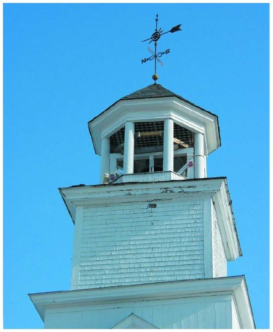
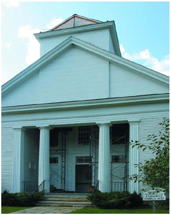
The Community Church at South Woodstock, Vermont, built in 1839 in the Greek Revival style as the South Woodstock Congregational Chapel, provides an example of a structurally deteriorated and failing steeple restored with the intent to reuse or repair the maximum amount of its historic material. Many timber elements from the 1792 South Woodstock Meetinghouse, then recently torn down, were included in the frame of the new 1839 structure. Most of the roof frame came from the previous church, reconfigured to a fashionable lower pitch and recut using the square rule layout method, which generally replaced the older scribe rule method of timber layout around the turn of the 19th century. The latter requires the laying of timbers against one another, and preassembly; the newer method allows the remote cutting of joinery and no preassembly. Signs of the scribe rule method such as unaccompanied marriage marks and empty joinery on kingposts and chords indicated timber reuse and the change in layout method.The first two telescoping levels of the steeple, however, were made of new spruce timber combined with hardwood bracing that carried the marriage marks of the 1792 scribed frame. The eight turned butternut columns that form the belfry level were from the previous church and carried the remains of elongated, steeply pitched joinery and relict hand-forged bolts that once fastened tall spire rafters. In our repairs, we managed to reuse parts of six of the original columns.
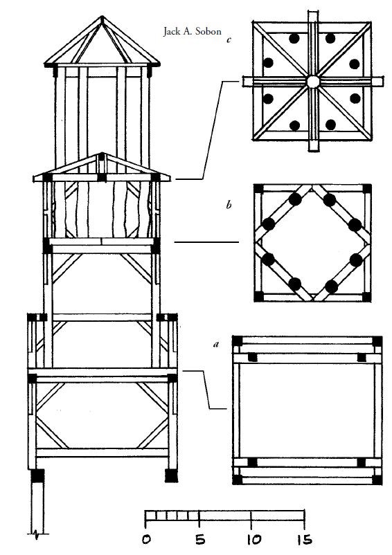
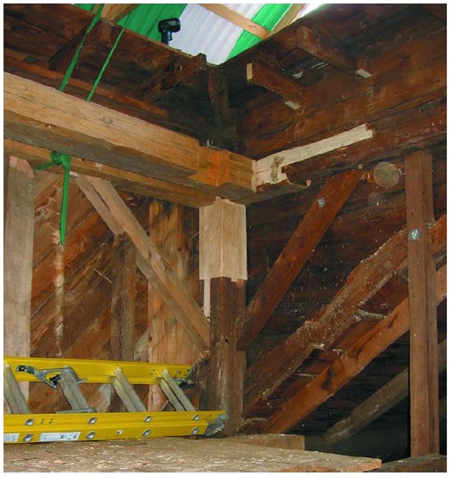
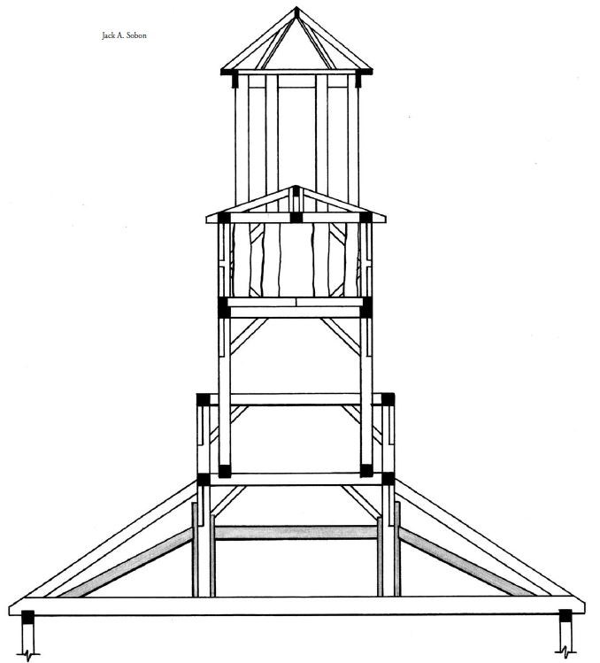
The 1839 church appears in 19th-century photos with its cur-rent more modest short cone of a spire; no historical accounts suggest any alteration of the original. Typical for the period, the steeple is fully engaged in the body of the church. Posts 15 ft. tall emerge through the roof to form a square tower. These four posts tenon directly into tie beams in the roof frame rather than tenoning into sleepers (or distribution timbers) that cross two or three truss tie beams, the more common technique at the time (Fig. 1). The front of the tower was well supported by the front wall of the church, but the rear stood over an open choir with an unsupported span of 42 ft. In an attempt to bridge this distance stiffly, the builders used the tower’s two rear posts as queenposts in the first roof truss, with principal rafters as main braces.
Jan Lewandoski
Some 8 ft. below the plates of the bell deck, four sleepers lodge diagonally across wall girts and carry eight butternut columns that surround the bell and support the short conical spire over the belfry (Fig. 1b). The 18-ft. butternut columns are notable for having been turned between centers to a tapering cylinder for their visible upper 10 ft. but left as debarked logs for their concealed lower 8 ft. The columns, thus rough and irregular for about half their length, nevertheless tenon into the sleepers in a regular layout governed by the central axis of their upper visible portion and the octagonal form implicit in the diagonal sleepers.
An original gin pole base, still in place across one of the corners of the second stage when we began work, suggested that the columns were brought up one at a time through openings in the bell deck. The lack of any joinery between the columns short of the spire framing, and a general lack of space, suggested that the upper octagon was not brought up from below as a whole, as was often the case in the erection of steeples.
Jan Lewandoski
The keys to dismantling, restoring and re-erecting any steeple are to understand its structural system and to interpret the original framer’s intent, then to assess which failures are ascribable to avoidable decay over time and which ascribable to original design flaws or undersized materials. It’s not uncommon to be confronted by framing that seems inadequate or baffling as to why anyone would do it that way. If the framing shows no evidence of stress other than decay or insect damage, however, it should be retained or reproduced in kind, regardless of odd joinery locations, small dimensions or low design values of the wood species.
Quantitative engineering of historic wooden steeples is of limited use since no convincing analytic models exist for their performance. Often the exercise is better avoided entirely. While a calculation can be made of a steeple’s overall weight, the effects of wind, and thus the impact on the sleepers or trusses that support it, looking for deflection or shear failure in the trusses or timbers can tell you as much or more. Quantitative analysis might suggest that a bearing member is overloaded or a vertical member is in danger of buckling failure but, if visual examination and measurement find no confirming evidence, you are wiser to have confidence in the thing itself rather than a theoretical model with excessively simplified assumptions about connections and load paths, and design values that may not accurately reflect the precise species or quality of wood or the snow and wind loading specific to the microclimate of the site.
Jan Lewandoski
Rather than opposing engineering analysis, I am recommending here the use of engineers, consultants or contractors experienced, or at least interested, in historic timber framing and willing to spend the time physically examining the artifact in great detail, not merely running the numbers. The appropriate form of engineering analysis for these frames that have endured the vicissitudes of existence for 100 to 250 years is qualitative. Analysis should proceed by looking for stressed joinery and excessive bending or buckling of beams and columns, or other evidence of progressive failure not attributable to water or insects, nor attributable to the unconsidered removal or severing of steeple structural elements by tradesmen, or to modifications made to the audience room below the steeple, such as the removal of galleries, columns or braces.
Jan Lewandoski
At South Woodstock, the key to understanding the steeple was to observe that the three stages are not interconnected but merely lodged on sleepers within each other, attached by no more than the nailed small lumber and flashing of their skirting roofs. Further-more, while the first and second stages are rigidly framed in them-selves, the butternut colonnade has no column-to-column joinery connections, although it picks up some rigidity where it passes through the boarding of the bell deck.
Consequently, our pulling away the flashing allowed a crane to lift off the conical spire, then the eight columns separately (they all needed repair or replacement), and then the entire second square stage, setting all in carefully prepared frames on the ground. On the same day, a light temporary roof (Fig. 4) was placed atop the first square stage (the tower), which would be worked on in place since large portions of the church roof still depended upon it.
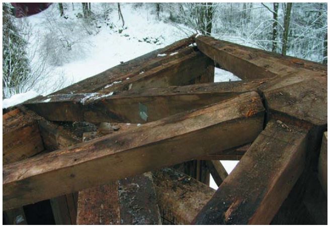
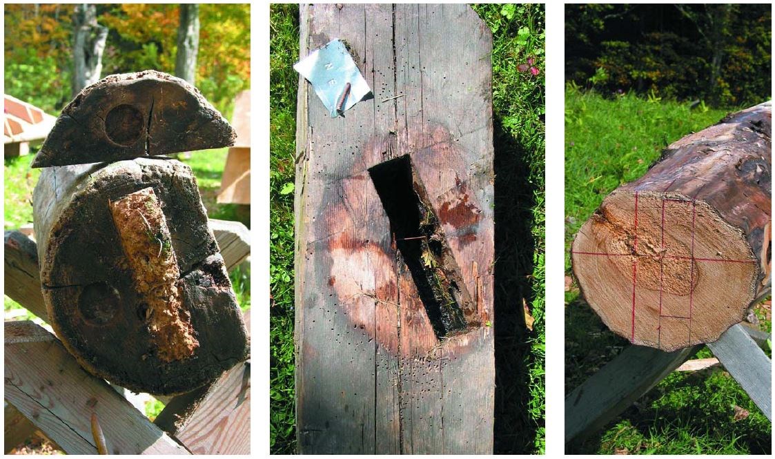
Restoration required copying the dimensions, species and joinery of the various members and reassembling them. The in-place tower called for extensive free and slotted tenoning since it couldn’t be fully pulled apart. We were free to rebuild the second stage, however, as it was originally built. The butternut columns were elaborately repaired and two replaced, although finding reasonably straight and sound 13-in.-dia., 18-ft. butternut logs was difficult because of the pre-sent diseased state of the species (Figs. 8–11).

Jan Lewandoski
Jan Lewandoski
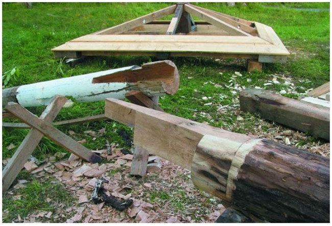
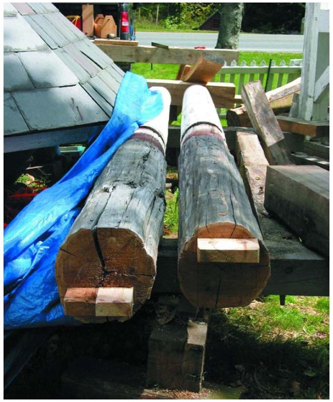
With the columns on the ground, we discovered the original turning centers, 2-in.-dia. holes 2 in. deep, giving us reference points for correctly locating tenons on the bottom of restored or replacement columns. An octagonal layout had been superimposed upon the diagonal sleepers, and mortises cut at eight regularly spaced points. We were able to cut (or insert) tenons on the bottoms of the columns at a regular offset from the turning centers to engage the sleeper mortises correctly to hold the columns plumb (Figs. 5–7, 10).
We made structural improvements only where excessive stress was observed. The truss supporting the back of the steeple was not stiff enough to help carry the weight of all the stages above in addition to its own significant roof load, and had sagged noticeably when we began work, a problem endemic to steeple supports of the period. (The resulting backward tilt of many 19th-century steeples is a common sight today in New England.) At South Woodstock, this problem was amplified by extensive water infiltration into the two tower sections and resultant rot. At South Woodstock, this problem was amplified by extensive water infiltration into the two tower sections and resultant rot.

Jan Lewandoski
Jan Lewandoski
We made structural improvements only where excessive stress was observed. The truss supporting the back of the steeple was not stiff enough to help carry the weight of all the stages above in addition to its own significant roof load, and had sagged noticeably when we began work, a problem endemic to steeple supports of the period. (The resulting backward tilt of many 19th-century steeples is a common sight today in New England.) At South Woodstock, this problem was amplified by extensive water infiltration into the two tower sections and resultant rot.
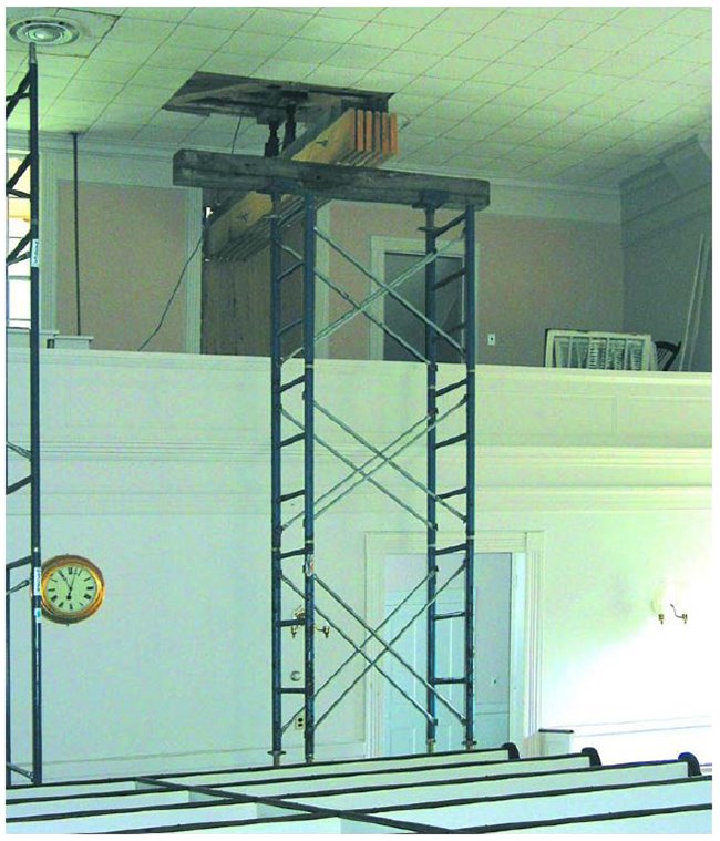
Each pair of scaffolding towers carried large built-up beams passing through the second floor windows of the front gable of the church. Screwjacks atop these lifted the sagged truss chord to slightly above level so that the additional queenpost elements could be installed and then loaded. We also increased the sleepers for the octagon columns from 7x9 to 10x11 inches in response to sagging observed in the originals. After completing repairs to the tower (Fig. 13), we lifted the ensemble, stage by stage, back into position.
Jan Lewandoski
The question of how much you can recamber any truss depends not only on the weight and stiffness of that truss and any super-imposed load such as a steeple, but on what else in the church you might be trying to drag upward with you. At South Woodstock, the front gable and the next truss in from the one we were improving were cambered slightly below level, so this set a limit to how far we could lift the truss located between the two. If screw-jacks that have been readily lifting a frame element abruptly become much more difficult to turn, don’t merely add more jacks at that location. Look to see what you are pushing or pulling with you, and either jack those adjacent elements individually or accept the level you have achieved.
Dismantling a steeple for the purpose of frame and flashing repairs also offers the opportunity to uncover changes in its form and finish that occurred over time. Decisions can be made (though not lightly, and with the participation of all vested parties) to return some portions of the steeple to an earlier configuration. In the case of South Woodstock, joinery for tall spire rafters existed, but the rafters may have been on the previous 1792 meetinghouse where the butternut columns had a former life. No images or descriptions of a former spire on the 1839 church existed, so any restoration would have been hypothetical and none was undertaken. On the other hand, the 1950s layer of white cedar shingles on the second tower level was found to cover a mostly sound finish of clear pine boards, 12–22 in. wide, hand planed, tongued and grooved, and mitered at the corners. Such flush boarding was typical of the Greek Revival and survived on the tympanum of the church. Since we had the artifact still in place, and 75 percent reusable, we left the shingles off and returned to flush boarding in our restoration.
STRAFFORD TOWN HOUSE.
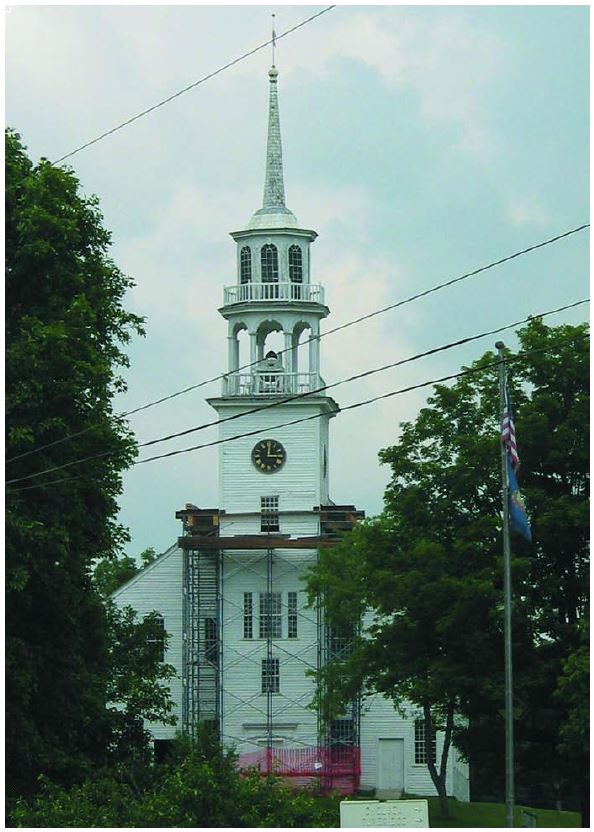
The Town House (1799) at Strafford, Vermont (Fig. 15, page 12), was built at the end of the period when New England town and church still shared financial and architectural resources, and the meetinghouse was used by both. With its steeple appended to the front gable of the building, not rising from the roof, the building’s design was also conservative, what Edmund Sinnott calls Type II in his 1963 survey Meetinghouse and Church in Early New England. Sinnott’s Type I is the square, hipped-roof meetinghouse of the 17th century that sometimes carried a small turret or cupola at its center, but no steeple. Type II is the oblong meetinghouse of the 18th century with a semi-detached steeple rising from the ground at one gable end. The mostly postrevolutionary Types III and IV show the steeple moved onto the body of the church, rising from the roof and portico or the roof alone, and are distinguished only stylistically as Federal or Greek Revival.
Jan Lewandoski
The Town House frame, its joinery laid out by scribe rule, is in a remarkable state of preservation. Even substantial areas of sawn white pine clapboard on the tower we found to be original, affixed with handmade nails, and in good condition. The trusses of this building have been discussed elsewhere (Lewandoski et al. 2006) and the entire history of the building, including design and construction, in Gwenda Smith’s The Town House (1992).
Jan Lewandoski
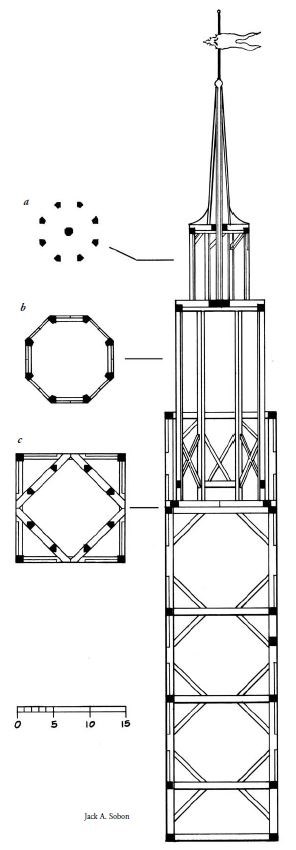
The steeple of the Town House comprises a 59-ft. tower, an octagonal colonnaded belfry rising from within it, a smaller octagonal lantern atop the belfry and 19 ft. of tapering spire exposed above that, capped with an ornament and weathervane (Fig. 15). Overall height is 115 ft.
The framing of the tower telescopes where exterior design allows. Belfry posts rise from diagonal sleepers 14 ft. below the roof of the tower (Fig. 16c). That tower roof is the bell deck as well, so that the weight and dynamic loads of the bell are borne first by cambered bell girts that cross the tower plates and then by the heavily braced framing of the tower below (Fig. 16). A horizontal timber crab (a frame with eight radiating legs) sits on top of the belfry posts, pro-viding a base for the eight wall posts of the lantern and footing for the mast (Fig. 17). The mast, a 12x12x30 timber, rises through the lantern and offers a center for the spire and anchorage at the top for the weathervane (Fig. 16).
Jan Lewandoski
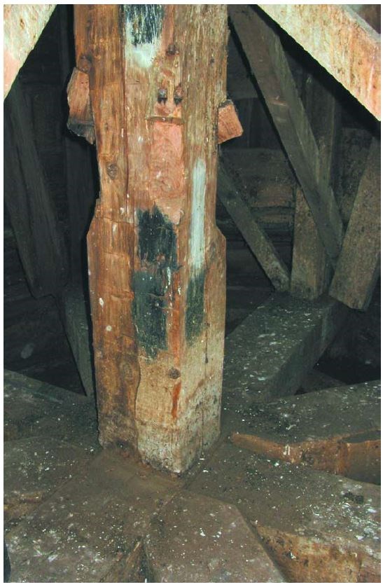
The framing of the Strafford steeple is very heavy and of thoroughly mixed species. The front tower posts, which go to the foundation, are 11x11x59 single sticks of chestnut. The rear tower posts of beech drop 30 ft. from the tower plate to tenon into the front gable tie beam of the meetinghouse. The horizontal tower girts, typically 10x11 and 15 to 16 ft. long, are of spruce, white pine and beech while the bracing and studs are mixed hardwoods including sugar maple, yellow birch, red oak and beech.
One level of tower girts carries the four belfry sleepers, 10x9 pine timbers, set diagonally across the corners of the tower, each with mortises for two belfry posts with lower through tenons, unpinned (Fig. 16). These belfry sleepers lodge on the tower girts, as is typical, neither lapped in nor affixed in any way. Today’s engineers, architects and contractors are usually shocked by this lack of a mechanical tiedown between telescoped stages, but my examination of 100 and more steeples indicates that uplift is not a problem at this location. Stages are better left only lodged, the intent of their historic engineering.
In carrying the belfry sleepers and posts, the tower girts also carry the lantern, spire, vane and all 68 ft. of framing and finish above. The main problem to be remedied at Strafford was the failure of tenons on three of the vital tower girts. The cause of this failure was two fold.
First, water infiltration at the front of the bell deck had run across the tower plate and down the posts. All being chestnut, they suffered little harm. The same water entering the mortises for the tower girts of spruce, pine and beech, however, caused their tenons to be weakened by decay, though not totally destroyed.
Second, the braces and studs under the tower girts supported the outer 4 in. of a 10-in.-wide timber while the load of the 68 ft. of structure above was delivered by the sleepers to the inner edges of these timbers (because load always goes to the first point of stiff-ness). Meanwhile, the tenons of these supporting girts, 2 in. thick, 11 in. tall and set 2 in. from the outside face of the frame, unassisted by any bearing housings for the girts, took the entire eccentric load.
Jan Lewandoski
With few exceptions, American scribe and square rule framers from the 17th through the 20th centuries located tenons a framing square’s tongue (1½ in.) or blade’s width (2 in.) from an exterior reference face, almost ritualistically and regardless of the tenon’s relationship to the forces it was expected to resist. At Strafford, with the weakened condition of the tower girt tenons, the eccentric loading and the absence of resistant bearing housings where the girts met the posts, rotation of the girts began to bend and break the tenons, threatening to drop the upper levels of the steeple.
Other problems at Strafford included a horizontal tower girt (not directly bearing upper steeple loads) rotted for half its length and needing a scarfed timber repair (Fig. 22 overleaf). The bell deck was leaking and in need of a new covering as well as replacement of some of its structural members, including two hip rafters.
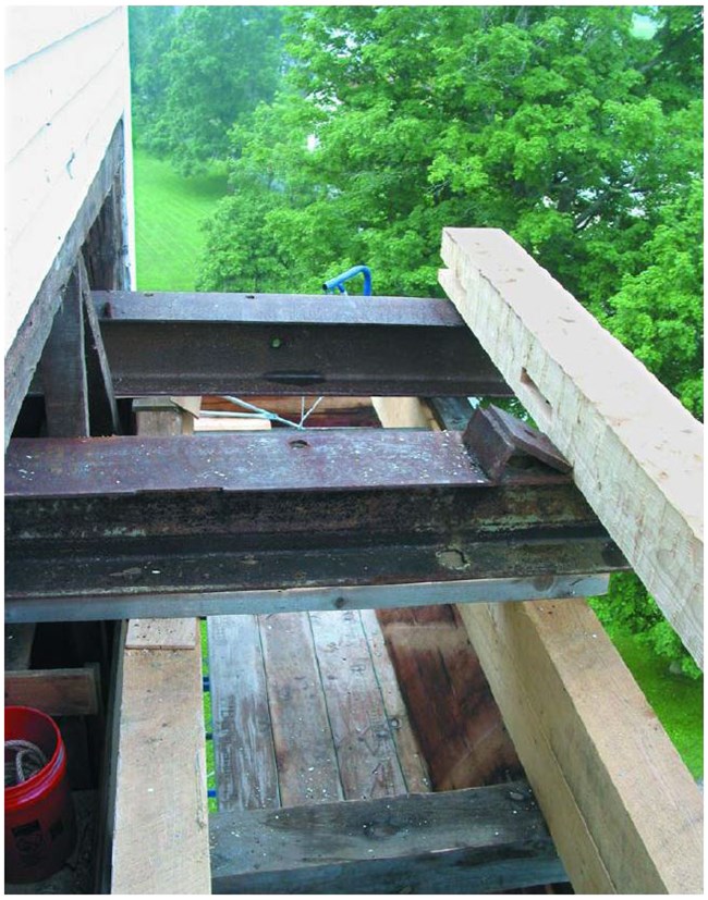
Since the belfry, lantern and spire were to be left in position at Strafford, the rigging problem was how to lift these upper stages off the tower girts that were failing under load. The solution was to erect 42 vertical ft. of tied-together structural scaffolding around all three sides of the tower, footed on good gravel. On top of the scaffolding at two opposing sides of the tower we established framed cribs, each composed of two levels of stacked 8x9x17 hem-lock timbers spread 5 ft. apart by tenoned 6x6s (Figs. 15 and 18).
Jan Lewandoski
By counterweighting the load from within the tower, we could slacken the crane’s lift line to free the beam tongs and shift them progressively outward, thus sending the steel inward. In this fashion we were able to slip three I-beams through the tower from crib to crib. At one point, the opening for the steel was so constricted by a sound diagonal brace we did not wish to remove that we moved an I-beam on oiled steel plates rather than 1-in. rollers, this small difference allowing us to get through the desired opening. A fourth position was too constricted entirely for the 12-in. steel, so we inserted a 7x13x20 yellow pine timber instead and, once it was in place, bolted on a 2¼x16 laminated veneer lumber (LVL) plank for further stiffness.
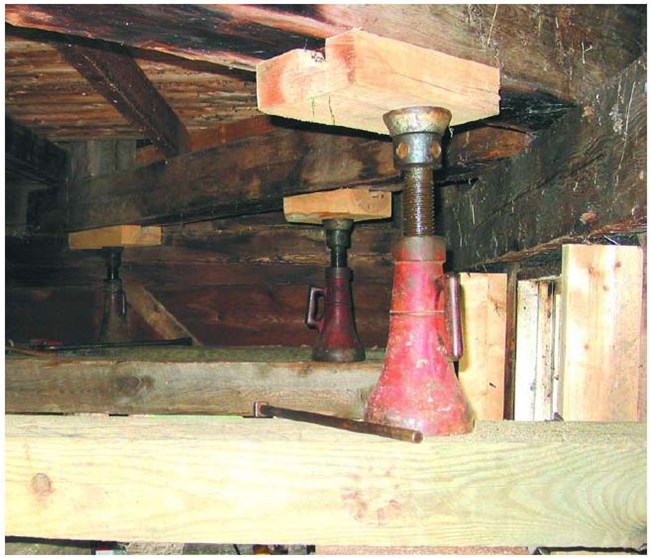
We placed heavy cribbing spanning the I-beams and 20-ton screwjacks atop these, pressing on 4x10 hardwood blocks under the belfry post positions on the belfry sleepers (Fig. 19).
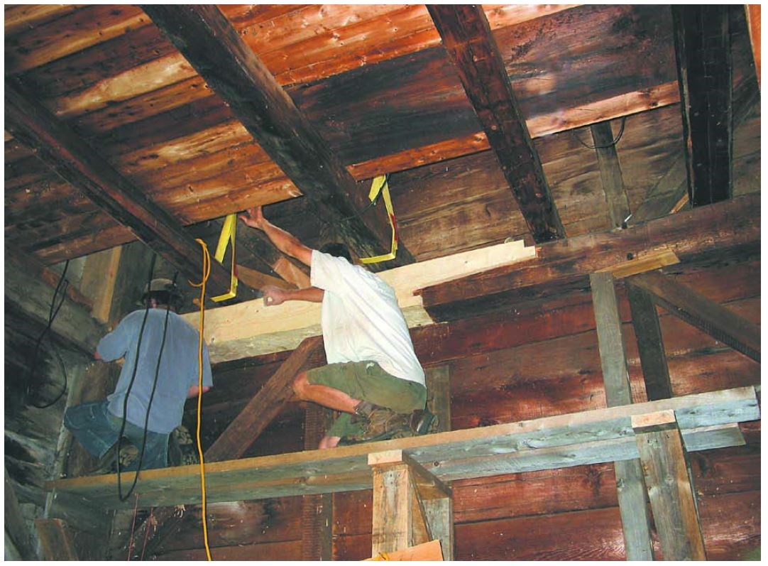
Turning these eight jacks at first deflected the I-beams a couple of inches and then readily lifted the approximately 20,000 lbs. of upper steeple off the girts. At this point we were free to cut out the damaged girts and replace them with new timbers (spruce of very high quality), free-tenoning one end to engage the fixed frame, and then repair or reposition the diagonal braces that rose to the girts.
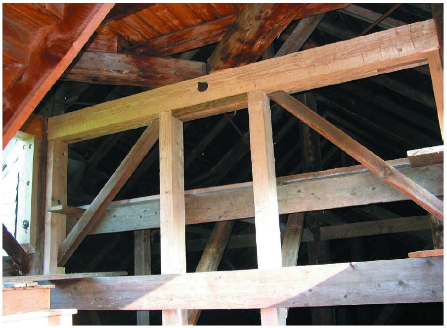
Photo: Jan Lewandoski
Resistance to the fatal inward roll of the girts, as well as support for the free-tenon ends, were provided by bolting 4x9 hardwood studs to the corner posts right under a girt joint to the post and at two additional locations under a girt where belfry sleepers bear (Fig. 20).
The same rigging and shoring we used at Strafford could be used elsewhere if horizontal sleeper timbers and post tenons were in need of replacement, as is often the case. Crossing steel I-beams with a grid of substantial plank or LVL lagbolted to the belfry columns will generally allow picking a belfry off its bearing sleepers if the pick points are reinforced above by blocks bolted to the columns or jammed against any upper girts between columns.
We reinstalled the several original clapboards with their original wrought nails on the east and west faces of the tower. On the south side, where more damage from sun and precipitation had occurred, we replaced the clapboards in kind with clear white pine, bandsawn with some taper and with a handplaned bevel along the top edge.
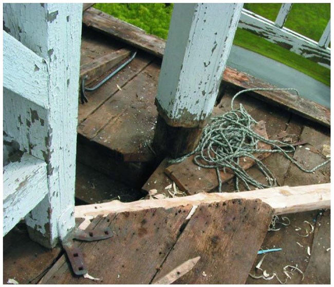
The bell deck was of great interest, with two versions still in place. The first, resting upon heavy bell girts crossing each other from the tower plates, comprised wide pine boards 1½ in. thick used in a sort of giant shingling (Fig. 21). The butt joints of these planks and the eight openings around the belfry posts had been caulked with oakum (rope fibers) mixed with tar, like the deck of a ship. However, unlike a ship’s deck, no large crew would check the condition of its oakum caulking every day, so this deck failed to keep water out. Another had been built on top of it using 4x5 hardwood rafters, pine and spruce boards and painted pine shingles. Sometime in the 20th century this second deck was covered with galvanized metal. Throughout these changes, the columns were kept well flashed where they passed through the deck, a com-mon locus of deterioration, and no problems occurred there.
Repairing the deck was straightforward. The metal and the wood shingles were removed, two hip rafters replaced in kind and the rotten boards renewed. The town had decided to try a mem-brane covering and a contractor laid it on ½-in. plywood so as not to attach it irreversibly to the historic bell deck. We left the original plank and oakum deck in place as a rare survivor.
––Jan Lewandoski
Jan Lewandoski operates Restoration and Traditional Building in Stannard, Vermont. Part of the South Woodstock steeple discussion was published in TF 84 in different form.
Jan Lewandoski
BIBLIOGRAPHY
Lewandoski, Jan, “The Erection of Church Steeples in 18th- and 19th-century New England,” TF 36, June 1995.
——, et al., Historic American Roof Trusses, Becket, Mass., 2006. Sinnott, Edmund, Meetinghouse and Church in Early New England, New York, 1963.
Smith, Gwenda, The Town House, Strafford, Vt., 1992.
