Last updated: July 7, 2021
Article
Timber-Framed Steeples - Middlebury, Vermont
HISTORIC AMERICAN TIMBER-FRAMED STEEPLES
I. Middlebury, Vermont
Timber Framing March 2007
This article is first in a series to discuss the form, function, and joinery of selected historic American timber-framed steeples. The series was developed from original research under a grant from the National Park Service and the National Center for Preservation Technology and Training. Its contents are solely the responsibility of the authors and do not represent the official position of the NPS or the NCPTT.
One of the peculiarities remarkable about Wren’s period is the investment of the form of the Gothic spire with a clothing of Italian Architecture, by which the modern steeple was produced. (J. Gwilt, The Encyclopedia of Architecture, 1867)
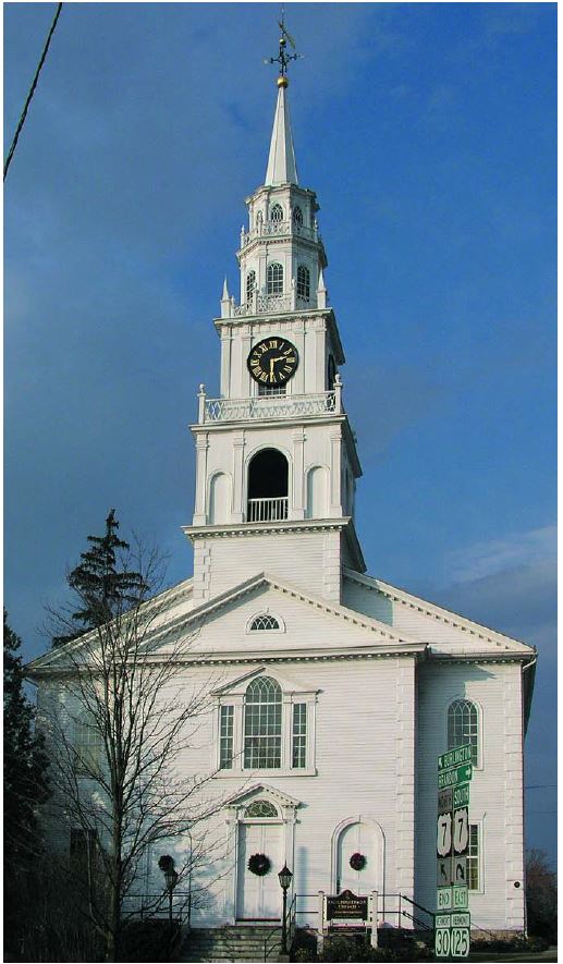
The tall, storied steeple of the Middlebury, Vermont, Congregational Church (1806-09) is an outstanding example of Federal architectural design and of substance and sophistication in heavy timber framing. The church is 59 ft. wide and a shallow porch protrudes 5 ft. forward across the central 34 ft. of the façade. A 17-ft.-square tower, or plinth of a tower, decorated with quoins, rises from the porch and from the frame of the roof system, with another 17-ft.-square tower, this one with ranked pilasters and arched niches, some open and some blind, rising another 14 ft. above that. This second stage of the tower may be called the belfry for it carries the large bell.
A square lantern of somewhat smaller footprint rises next, with ranked, fluted pilasters and large clock faces, added in 1853, that unfortunately interrupt the original design of ascending arched windows. Above that, the first octagonal lantern emerges and then a shorter octagonal lantern above that with elliptical fenestration. This second lantern is surmounted by a spire, ball, and vane, of which the comet-form arrow is itself 6 ft. long. The overall height to the top of the vane is 135 ft., but the church’s position at the crest of a hill above the center of the village makes it appear taller (Fig. 1).
Middlebury’s architect was Lavius Fillmore, self-taught, with origins as a master framer of churches and other large structures. The actual framer appears to have been one Martin L. Crandal, who advertised in the local newspaper for “15 journeymen joiners” (Middlebury Mercury, Feb. 5, 1806). Glen Andres’s extensive research on the origins of the Middlebury design and its development from Fillmore’s other churches in Bennington, Vermont, and East Haddam and Norwichtown, Connecticut, will give a much fuller picture of the architecture of this structure (Andres 30-42).
The exterior design of Middlebury’s steeple is based on the works and publications of the British architects James Gibbs, Christopher Wren, Robert Hooke and Nicholas Hawksmoor, and their American successors such as Joseph Brown.
Similar designs, previously rendered in masonry in England and continental Europe, are here translated into wood, as was done by Brown in his First Baptist Church of Providence, Rhode Island. Each story is deeply telescoped into those below it and, while the telescoping itself is normal for the period, the great density and interconnectedness of the Middlebury frame is remarkable. Unlike the derived architectural style of the steeple, its framing is reflective of a region possessing vast native supplies of extremely large, old-growth timber. Fillmore and Crandal’s attempt to produce an immensely weighty and relatively inflexible very tall object set it apart from many other steeple frames of the period that have quite opposite aims, namely lightness and flexibility.
Middlebury’s timber is all oak (red and white) and pine (white and possibly red). Many of the largest sticks such as truss chords and tower posts are hewn pine, but as often the tall posts are oak. The timber, almost free of wane and with few knots, is hewn and sawn to great smoothness and regularity. All the smaller timber, such as for braces, is oak, vertically sawn. There is plenty of evidence of both the square and scribe rules at different points in the steeple; when making unique assemblages in a frame, there is no special virtue to the square rule. Some of the largest columns in the tower, 12x12x28 and larger, carry Roman numerals matching those on the crib timbers they bear upon, possibly related to the order of assembly in this complex frame as much as to scribing.
THE STRUCTURAL FOUNDATION.
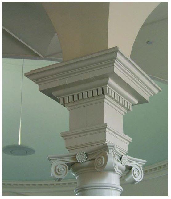
Middlebury’s weighty steeple is integrated with the exterior and interior design of the church. The front of the tower appears to rise from the front wall of the portico, although the two front tower columns disappear from sight descending inside the portico wall, dropping ultimately to the sill and limestone foundation at grade, a feature shared with Brown’s First Baptist of Providence. Longitudinal 12x14 main sleepers tenoned into these front posts right above the interrupted portico plate cross the 11x13 front wall plate of the church 5 ft. inward, and then the fully supported vestibule wall 12 ft. farther inward, ultimately terminating over the lower chord of the second interior kingpost truss. This truss is in turn propped by colossal columns rising through the audience room, supporting the galleries, passing through two levels of decorative capitals and tenoning into the truss several feet to the outside of the sleeper (Fig. 2).
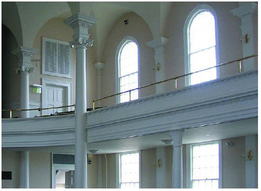
The rear columns of the first stage of the tower rise from these main sleepers slightly forward of where the latter cross the first interior truss. As is common in steeple framing, these posts are treated as queenposts in a truss to help carry the steeple load, but in this case the main braces rising to the tower queenposts are slightly out of plane, originating as they do on the truss chord centered 1 ft. behind the centerline of the posts on the sleepers. This combination of support systems for the steeple—portico plate, front wall, sleepers, vestibule wall, queenpost trussing of the rear columns and colossal columns assisting both the first and second interior trusses—apparently was not enough to stop some rearward lean of the steeple. The evidence is open (and now filled) joinery shoulders on the slack side, and the presence of later-added timber bracing on the compression side, the latter rising from the sleepers and first and second interior truss chords to the rear tower posts.
While backward lean is common in steeples where the rear of the steeple bears on an open span truss unsupported by intermediate walls or columns reaching to the ground, the declination of the rear of the well-supported Middlebury frame may be a result of combined factors: accumulated shrinkage of the several layers of timber supporting the rear, shrinkage across queenposts (which allows the truss to sag to take up slack in its compression joints), minor bending made possible by the small offsets between truss chord, sleeper and queenpost and, finally, even the out-of-plane configuration of the queenpost main braces. The kingpost truss right behind the tower queens can also be expected to sag a bit from settling and shrinkage across the broad head of the kingpost and across the feet of the low-pitched principal rafters and their chord ends. Shims in the kingpost truss joints indicate that their share in the problem has been jacked and partially remedied at least once in the past.
The tall front columns of the steeple rest directly upon a sill (invisible but likely 10 to 12 in. tall) at the foundation, but the rear columns bear first upon a multiplicity of deep sleepers, truss chords and truss elements capable of shrinkage and great compression from oblique bearing and bending moments, before their load is carried down to the foundation. The sum of horizontal-timber depth immediately under the rear steeple posts is 27 in., and the cross-grain shrinkage of this pile of oak, about 2¾ in. from green to dry, is augmented by wall plate shrinkage where the trusses bear, as well as the other sources of deflection cited.
Evidence that the rearward sag in the Middlebury steeple should be attributed to shrinkage is the observed incipient failure in tension perpendicular to the grain of the top surface of the east sleeper’s tenon in the front column, a consequence of the beam dropping relative to its tenon and the pins that transfix it. While timber is famously resistant to such failure, distortion first shows up as local bending of the member and compression in the bottom edge of the vertical tenon. Fortunately, the tenons are assisted by original ½-in. x 2-in. iron straps 36 in. long, fastened by six large hand-forged spikes, helping to tie the joints. Shrinkage of the 13-in.-deep front wall plate 5 ft. inward of the tower front, and then roughly twice as much shrinkage (based on 27 in. of timber depth) another 12 ft. rearward at the rear tower columns, would account for a gradual decline of the tower to the rear. If truss sagging or another problem at the rear of the steeple were the only problem (as it usually is), the sleepers would be cantilevered across the fully supported front wall plate and their tenons would be forced upward into their mortises in the front columns rather than dropping downward as they can be observed to do. The sleeper appears to be dropping downward at the face of the mortise, leaving its cracked upper portion behind, hanging on a pin.
If 12x12x60 timbers are available to stand upright, their potential aid in assembly and lifting and their advantages in axial loading, lack of shrinkage, and increased stiffness and stability of the tall object to be framed are hard to ignore. However, the framer has to balance the absence of both shrinkage and side-grain com-pression at the gloriously simplified front with shrinkage and com-pression at the complex rear of the same frame.
It is difficult enough to get the right initial amount of camber in trusses, allowing for later shrinkage and compression. In the usual steeple situation—front wall posts as tall as the side wall posts and a front plate as large as the truss bottom chord, so that shrinkage of the underlying support is equal front and back—the problem is then produced at the rear by truss sagging and shrinkage, or bending of the bottom chord when loaded between points of support.
At Middlebury, the tall posts complicate matters. For the tower base to come level after seasoning, the front wall plate 5 ft. in from the front columns would have needed to be made taller (deeper) to begin with, or columns within the front wall allowed to rise directly under the sleepers to support them pitched upward to the cambered trusses. The result would have been a steeple frame pitched slightly forward when new, waiting for years to settle to level.
THE TELESCOPING FRAMES.
The interpenetration of tall exposed frames into the frames or masonry stages below them is common worldwide in churches, temples and other tall structures, and good practice even for the cupolas of large New England barns, where cupola posts often drop 12 to 16 ft. below their apparent perch on the roof to tenon into heavy timber sleepers crossing two or three upper tie beams. Steeples without some degree of telescoping among the stages are rare, possibly because of the high tendency for those stages to be blown off by calamitous winds in the absence of some other anchoring measure or a benign topographical location.
There are two general strategies of telescoping, with many variants. The first inserts a stage for a relatively short distance within the previous stage and links the two tightly with girts, bracing and skirting roof framing, restraining the upper stage mostly by attachment to the mass of the lower stage, a sort of vertical cantilevering or anchoring. The second strategy inserts an upper stage deeply within a lower stage, perhaps establishes extensive bracing among the upper stage posts inside the concealed space and is only connected to the lower stage framing or masonry incidentally by flashing and small dimension roofing materials. In the second case, the upper stage mostly restrains itself by having a greater portion protected from wind pressure than the exposed portion. The framers at Middlebury, leaving no stone unturned, no opportunity unexploited, used both strategies.
The six stages of the Middlebury Congregational Church steeple comprise three square frames, two octagonal frames (the upper and lower lanterns) and a culminating tapered octagonal spire (Figs. 3 and 4).
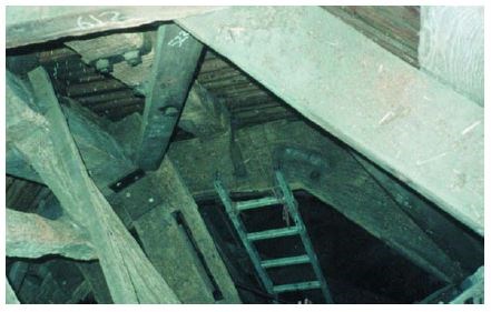
Tower and belfry. The first and second stages, respectively the tower plinth and belfry, although visually separated on the exterior by a large cornice and distinct architectural detail (Fig. 3), are sup-ported by the same tower frame: 12x12x60 tower posts rising from the sill at the front and 12x12x30 rear tower posts rising from the main sleepers and complex framing. Where tower plinth becomes belfry at the top of the first stage, the immense bell deck sleepers are lodged on two levels of 10x12 girts joined by short struts and sup-ported by long 4x6 oak braces (Fig. 5).
The five parallel bell deck sleepers run transverse to the axis of the church and parallel to the swing of the bell. They increase in size from the outside to the middle, becoming as large as 18x22. These timbers are sized to span the 17-ft. width of the tower and carry the weight of the bell and its dynamic loads. They also serve as bearing for the 28-ft. columns that frame the third square stage next above and, with the help of the mast, transmit all the loads from the remaining stages above.
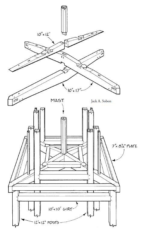
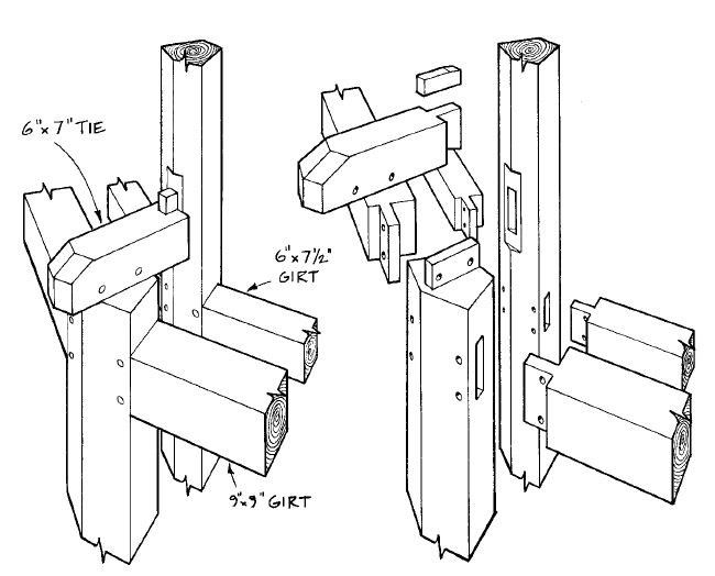
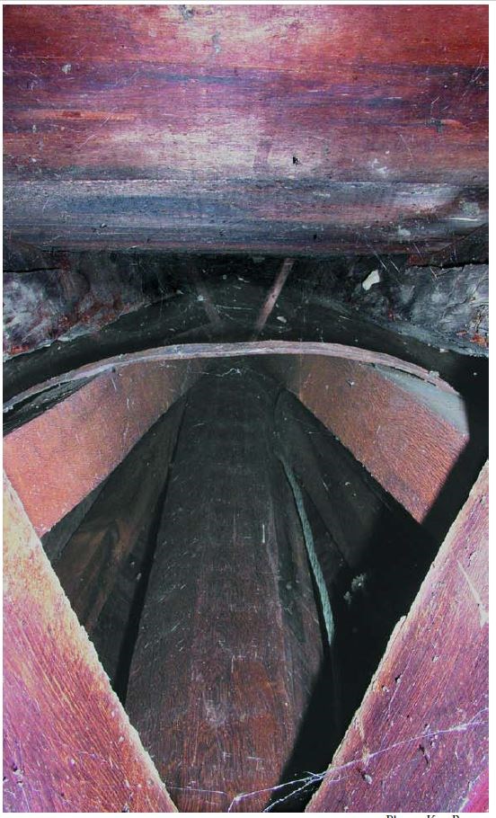
At the top of the belfry, the tops of the four corner columns of the tower are joined diagonally by the immense lapped double-cambered ties of the original mast base, which sit upon the post tenons. Girt timbers 10x10 tenon into these posts slightly below their tops and are double-braced by two different lengths of parallel 4x6 bracing (Fig. 6).
Clock stage. The third stage, the clock stage, is still square in plan but smaller than the tower and belfry stages, though architecturally similar. Since 1853 it has displayed the clock, perhaps enhancing the timeliness of the citizens, but interrupting the graceful vertical development of Fillmore’s design by almost entirely occluding the arched windows behind the clock faces (Figs. 1 and 3).
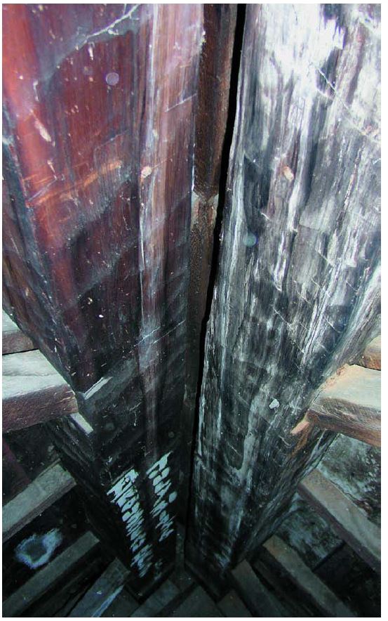
The eight 12x12x28 columns flanking the corners of this stage began approximately 14 ft. lower at the bell deck sleepers, rose hidden within the belfry interior sheathing, and now emerge to view as the visible steeple frame for another 14 ft. (Fig. 21). As these paired columns emerged from the belfry roof, they clasped the immense diagonal double-cambered ties of the original mast foot (Figs. 6 and 11).
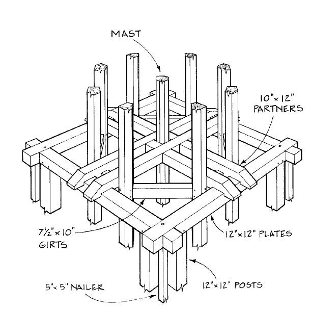
The four pairs of columns terminate in a 12x12 plate at the top of the clock stage. At this level, 10x12 mast partner timbers lap into and over this plate, two on each side. These partners clasp the mast at their middle and also lap over connecting girts within the fourth stage framing, the first octagonal lantern frame, already tele-scoped within the clock stage at this point. To add complexity to this junction, the crib timbers for the fifth stage, the second lantern, bear upon these partners, locking the lap joints with thou-sands of pounds of superimposed weight from the stage, spire and vane above (Fig. 7).
First octagonal lantern. The fourth stage, the first octagonal lantern, has the first true octagonal frame. (The clock stage below, though square on the exterior, is actually framed with eight posts forming an irregular octagon.) Its posts began in mortises at four crib timbers lodged upon the large double-cambered beams of the original mast foot at the top of the second (belfry) stage. This first octagon is telescoped within the clock stage for 15 ft. and then emerges for 12 ft. as a windowed lantern 9 ft. 8 in. across the flats. About 9 ft. up on each of the five-sided octagon posts, still within the clock stage, 3x5 diagonal braces rise and tenon into the eight facets of the mast, all the tenons being wedged at both ends.
Shortly above that point the pairs of octagon posts are joined by pairs of crossing braces (X-bracing) that tenon into the posts them-selves at their feet and the octagon connecting girts at their tops—the same connecting girts lapped by the partners mentioned in the discussion of the clock stage. This lantern’s five-sided posts pass through the partners, snugged against the outside of each member of the pair, rise 12 ft. and terminate in a short tie. Just below the tie lies a girt lapped by another set of partners, lapping a second octagonal lantern girt as well and clasping the mast (Figs. 8 and 16).
Second octagonal lantern. The fifth and last stage before the spire is the upper octagon, with its elliptical fenestration. Its eight five-sided oak timbers began approximately 11 ft. below within the lower octagon, at the crib timbers atop the partners at the top of the clock stage (Fig. 6). This upper octagon has become smaller, 7 ft. 3 in. wide across the flats, and exposes 9 ft. of height to wind and view. X-bracing and connecting girts lie right beneath where it emerges, and the set of partners that laps into the lower octagon plate also laps over these connectors before clasping the mast (Figs. 8 and 16).
The interior of the exposed portion of the upper octagon is full of diagonal braces, 16 of them dividing the space. Eight 3x4 braces rise from mortises in the mast and tenon into the inside faces of the five-sided octagon posts. Only 2 ft. above these latter connections, another set of eight braces rises from mortises in the posts to tenon into the bottom of the crab that ties together the plate level of the stage and also serves as the base of the spire framing.
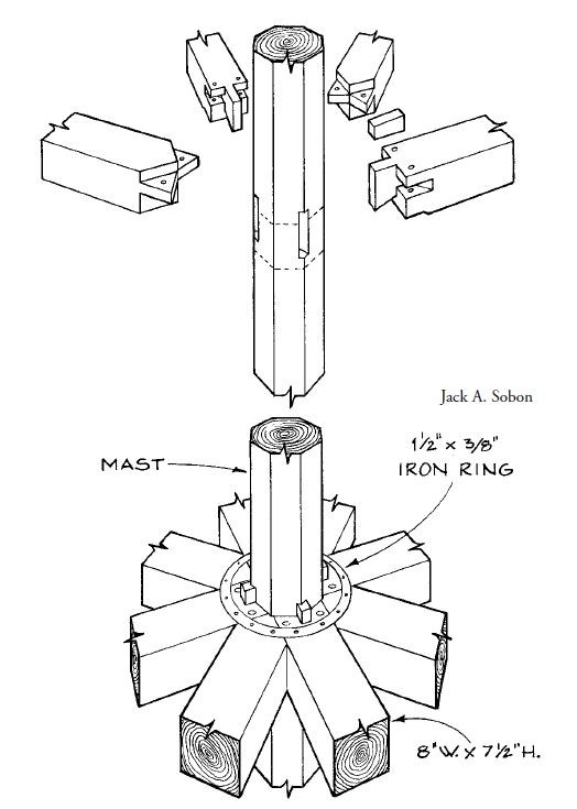
The eight legs of this uppermost crab, or star as it is sometimes called, join ingeniously to the mast and can be seen as interrupted tie beams across the octagon. The rigidity of this crab is reinforced by a ⅜-in.-thick iron ring set 4 in. away from the mast, crossing all the legs and spiked to each of them twice (Figs. 9 and 18).
Spire. The sixth and final stage is the tapering spire itself, amounting to 19 ft. additional of framework plus the 20-in.-dia. ball and 10 ft. more of weathervane. As often in spires, this stage is dense with framing. The octagonal mast rises undiminished through the spire to its top where it supports the ball and vane. Oak spire rafters 3½x4 descend from the top to bear in wedged mortises in the crab atop the upper octagon. Just 3 in. inboard from these rafters, eight identically sized oak braces rise from wedged mortises on the crab legs, 19 in. out from the arises of the mast, and climb a slightly lesser angle to mortise into the mast 9 ft. 10½ in. above. A hammered iron hoop binds the eight inner braces about 9 ft. above the crab. There appears to be another iron hoop around the spire rafters toward the apex, but the space is too full of timber to permit direct examination.
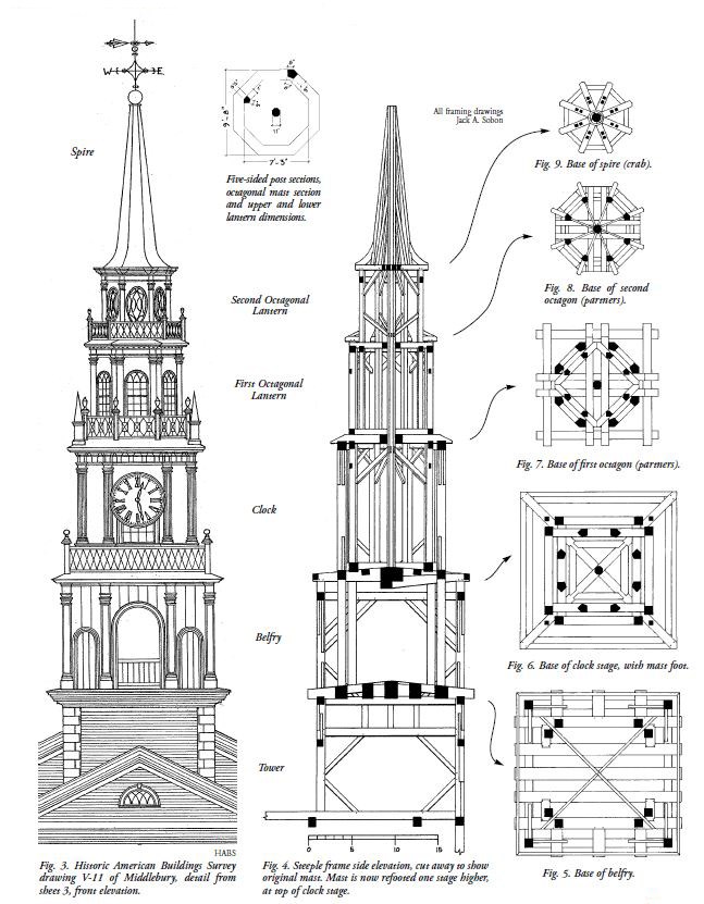
Fig. 4. Steeple frame side elevation, cut away to show original mast. Mast is now refooted one stage higher, at top of clock stage.
THE CENTRAL MAST.
The Middlebury steeple has a tall central mast of oak, originally footed at the top of the belfry and now beginning above the clock stage, that ultimately supports the ornaments and vane at the top of the spire. The mast is octagonal for its entire 53-ft. 2-in. length (as calculated with the aid of Historic American Buildings Survey drawings), and measures 11 in. across the flat faces. It is pierced by 32 mortises accepting bracing and crab timbers and also clasped by double pairs of partner timbers at two different elevations, forming, with the diagonal crib timbers lodged upon them, another sort of octagonal bearing as well.
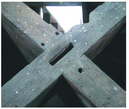
The mast was originally footed with a tenon on a crossed pair of immense timbers, cambered both top and bottom, forming the roof system over the belfry (Figs. 10–11).
Timbers this size, each cambered to 10x17 at the crossing and one augmented on top by a cambered 10x12, are usually reserved to carry the weight and dynamic loads of a bell, not the lightweight roof over it, so it can be supposed that the framer thought one of two things: first, that the mast might permanently carry the accumulated load of the three stages and spire forming the upper 54 ft. of the wooden structure; or, second, that the mast was to be erected, somehow braced, and used as a lifting rig (or at least a stabilizing axis) for these upper levels.
If Fillmore and Crandal believed the first, they were proved wrong by 1853 when the base of the mast was cut off about 9 ft. above its bearing point to make room for the clock shafts. This offcut base segment lies about 3 ft. away from its original mortise, carrying some flooring today. The great number of braces, crabs and partners proved adequate to keeping the mast in place, so that while it isn’t pendant (hanging unsupported from the apex, as the mast is in some other steeples), it’s no longer footed either, and none the worse for it.
The second possibility, that the mast functioned as a lifting rig for its surrounding framing, and thus temporarily bore great loads, remains a conjecture. The great density and interconnectedness of the framing makes it unlikely that the various frames were brought up whole from within, as is known to have been done elsewhere, for example at the Strafford, Vermont, Meetinghouse (1799) and the Centre Church (1812) in New Haven, Connecticut. At New Haven, we have eyewitness accounts of such a raising and, at Strafford, three out of a set of four gin-pole bases are still in place at the corners of one tower level to carry out the sort of full-stage lifting for which contemporary accounts exist (Lewandoski 6–7).
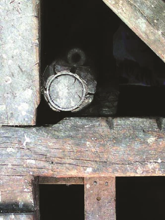
At Middlebury, however, large pieces and partial frames may have been erected and stabilized by the mast during assembly. A relict gin pole, a single 15-ft. piece of 5-in.-dia. ironwood (hop hornbeam) with an iron-bound top and eye bolt for rigging, left embedded at the level of the clock, suggests that lifting was also being done by something additional or combined with the mast (inset photo). This gin pole may have been attached to the mast as a jib, allowing the rigging to reach out over the side of the tower to snatch loads from below. Square reliefs cut out of horizontal timbers at several upper levels also suggest that individual large timbers were brought up right through the partially completed frame.
THE CRAB.
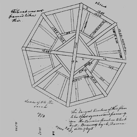
In timber framing, “crab” refers to a horizontal frame with eight legs or regularly spaced points of bearing or tying, flat or slightly cambered, sitting atop the posts of one octagon and sup-porting the posts or rafters of another. The term has historic credentials. The Burlington, Vermont, framer John Johnson drew and labeled crabs and specified them in his lumber lists for the Orleans County Courthouse (1816) in Irasburg, Vermont, as well as for an immense one, 34 ft. across, for the octagon atop the Centre College building at the University of Vermont in Burlington in 1829 (Fig. 12).
Robert Smith’s St. Peter’s Episcopal Church in Freehold, New Jersey (1771), has a typical crab (though we don’t know what he called it). In French work, several types of crabs as well as partners were used and illustrated, and called enrayures, a term also used for the spokes of a wheel and for a plate system in complex roofing not limited to octagons (Fig. 13).
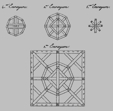
As long as octagons have needed bearing or tying, some form of crab has been in use. In his surveys of British carpentry, Cecil Hewett doesn’t use the term crab but illustrates one exactly like those common in the 18th and 19th centuries in America, with four long legs and four short, in his drawings of the southeast spirelet of Canterbury Cathedral, Kent, which he dates to the 12th century. Hewett uses the term star for another sort of eight-legged figure where all the legs radiate from a common center, with the crowded joinery or metalwork that this entails, at Canterbury Cathedral (Hewett 1985, 139). The latter sort of crab is in use at Middlebury.
The oldest wooden spire I have examined, the 13th-century Church of St. Mary the Virgin at Cleobury-Mortimer, Shropshire, England, has an eight-pointed star or crab footing the mast and tying the rafters. Elsewhere in this spire naturally, curved timber is used to provide eight points of bearing and tying. St. Mary’s octagonal spire has lines of four long spire rafters joined by horizontal girts with a natural 45-degree crank, the projecting mid-sections mortised, providing bearing and a tie for shorter rafters and producing four more arrises for the spire (Figs. 14–15).

The second method was a bi-level sort of crab based upon two, or two pairs of, timbers crossing the octagon at right angles to each other and another square of sleepers or crib timbers lodged diagonally on top of these. The upper level carries the eight posts. Compress the two levels into one and you have a crab. This type of crab is found in Middlebury over the belfry at the massive base for the mast, on which are lodged the sleepers for the lower octagon frame (Fig. 11), and found again at the bottom of the upper octagon, where short ties connect the tops of the posts of the lower octagon with the midheights of the posts of the upper octagon and parallel sets of ring girts connect the respective post sets (Fig. 16).
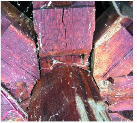
The third type of support is found at the bottom of the clock stage (or top of belfry), which has eight corner posts but expresses itself on the exterior as a square (Figs. 6 and 11). These 12x12x28 posts begin 12 ft. below on the mighty bell deck framing, where five pine sleepers as large as 18x22 span the 17-ft.-square tower. Four of the posts land directly on sleepers and four on short dove-tailed 12x12 connectors between sleepers (Fig. 5). Slightly separated in each pair and flanking each corner as seen in Fig. 21, the posts clasp the diagonal crossing timbers of the belfry roof as they pass and support large mast partners at their own top-plate level.
This immense expenditure of timber and mass may have been used to anchor and clasp the mast that was by some powerful rigging erected within it, the mast finally projecting out almost 40 ft. above the partners at the top of the clock stage. The mast could then be used to lift the framing of the two octagonal stages and the spire by means of block and tackle.
THE PARTNERS.
In naval architecture, partners run athwartships in pairs and clasp the masts to keep them upright. The mast itself is footed as well, somewhere deep in the vessel. Partners that clasp the masts of church steeples are framed similarly. Church spires, many of which have masts within them, may appear to spring from the top of the highest lantern or belfry, but this is usually not the case. Rather, the typical spire rafters are tenoned or spiked to facets (usually eight) at the top of the mast. The rafters then foot them- selves on a crab or octagonal plate, or a square plate level at the base of the visible spire. These rafters may also attach to the mast with nailers or mortised girts and bracing on their way down. The steeple mast itself may descend another 10 to 30 ft., concealed within the lower stages of the steeple and stabilized by partners, which run side to side between the major framing members and half lap each other at the middle, leaving a square space in which the mast is clasped. Consequently, the tall and slender mast and spire are restrained by the rigidity and mass of the bulkier lower stages. At Middlebury, two levels of partners—one at the top of the clock stage (base of first octagon) and the other at the top of the first octagon (base of second octagon)—are not designed to tenon into posts or arrive at a panel point, nor to be expressed in the exterior finished form of the steeple, but instead are opportunistically attached to the framing of the two surrounding telescoping stages and correctly spaced to clasp the mast (Figs. 19 –20).

Though it represents excellent practice in a building designed to endure indefinitely, partnering a spire mast as if it were a ship’s mast carrying sail would be undertaken only by the most conservative of framers. Sails are designed to invite tremendous wind pressure, an octagonal spire, close in form to a cone, experiences relatively little. Many spires are built without masts; either the rafters themselves start some distance lower in the steeple stages, or they spring from the top of a belfry where they are usually bound with long iron rods anchored deep within the steeple or with metal dogs or straps to a heavy plate and buttressed by a skirting roof. From a framer’s point of view, the functions of a mast may be multiple: part rigid restraint, part inward moving of the spire’s center of gravity, part structural focus for framing the upper stages in a unified fashion. The mast also may be an aid in erecting the spire if the latter’s parts come up from below and within. If the mast is not partnered or footed, it may provide a mysterious pendulum action to stabilize the tower. (Except in very tall and large spires, the partners may have more purpose during erection than during the life of the spire.)

At Middlebury, however, the ambitious goal was rigidity. The partners, clasping the mast and then engaging laps in the girts and plate level of the two surrounding telescoped stages, are bound down into these lap joints by the crib timbers of the next octagon stage, carrying the many thousands of pounds of weight of the 30 or 50 ft. of steeple, respectively, remaining above them.Even the spire, a 19-ft. tall tapering octagon with low wind resistance, centered on a stout oak mast virtually buried in 34 ft. of timber work below, is framed for rigidity. The spire rafters and an inner set of rising braces (half the rafter height and with a different slope) share a common wedged mortise on the tie beams of the spire crab. The curving skirt of the spire is framed of 3-in. plank let into rather than tacked to the rafters, another form of buttressing (Figs.18 and 22).
I HAVE emphasized Middlebury’s rigidity through this discussion because its steeple is indeed rigid relative to the other 100 or so wooden steeples I have examined in the last 30 years, and reflects the apparent intentions of the designer and builder. While surveying the steeple, even with our shoulders pressed up against the spire base (about as high as average adults could go), three per-sons moving in unison to produce sway in Middlebury’s massive interlocked timber construction were rewarded with very little, far less than the stomach-unsettling amounts that can be produced easily in most tall wooden steeples. But being slender and framed of timber allows even this steeple to be somewhat flexible as well, with the benefits that swaying rather than breaking convey, but rather less so than most other wooden steeple designs.
The notable steeple at the Federated Church (1832) in nearby Castleton, Vermont, is a contrary but also successful design. Almost identical in height to Middlebury, and with even deeper telescoping onto lodged crib timbers, Castleton’s elements are so little interconnected that they could be lifted apart for repair into three discrete units, each 30 to 50 ft. tall, with only the dismantling of flashing and lightweight nailed skirting roofs. The tele-scoping at Castleton is remarkably deep, with the belfry columns beginning 28 ft. below where they emerge from the tower. Likewise at the Congregational Church (1861) in Stowe, Vermont: there the feet of the four sets of paired columns of the belfry originate within inches of the bases of the 22-ft. tower posts and rise an additional 16 ft. above them. However, the only connections between the inserted stages at Castleton, Stowe and many other late-18th-century and 19th-century steeples are the cornices and the boarding and the small, usually nailed, rafters of the skirting roofs. Even at their bases, the columns of the various stages are tenoned into sleeper timbers that are merely lodged, not framed into or mechanically connected to the timbers they rest upon. (This last is true at Middlebury as well for the upper stages.)
At Stowe, the first three stages all clasp the 100-ft. tall central mast with partner timbers, and thus have an indirect connection to each other, but their purpose is to counterpoise the tall mast and spire, not to link to each other. Middlebury’s stages are deeply tele-scoped, but the frames of the interpenetrated stages are connected to each other and the mast with substantial framing and joinery every few feet. At four locations, joinery attached to the central mast connects rigidly with the plates and girts of two surrounding telescoping stages.
MIDDLEBURY’S TRUSSED ROOF.
Though our subject is steeples, it would not do to leave the reader curious about the trussed roof system of this 59-ft.-wide church. The trusses are impressive and adopt several forms to accommodate the 32-ft.-dia. globe arch (dome) in the center of the main room (Fig. 24), a feature the architect Lavius Fillmore also included at his meetinghouse at Bennington, Vermont (1805), and framed similarly.
The truss work at Middlebury does not rival the density or complexity of its steeple frame, like Bennington’s supported at the front on sleepers tenoned to continuous posts rising from the foundation. The Middlebury kingpost trusses are almost identical to those found at Bennington and at Fillmore’s Norwichtown, Connecticut, Meetinghouse (1801), and similar to those (also assisted by colossal columns) found in his East Haddam, Connecticut, Congregational Church (1794), where many of Middlebury’s interior design elements appear also (Kelly, 109-117, 119-128).
The roof frame at Middlebury is formed of kingpost trusses on regular centers, with one exception, where the dome projects into the middle of the attic beyond the third interior truss from the front. In this space approaching 40 ft. long, where two transverse trusses are expected, there is only one, a raised-bottom-chord king-post truss centered, according to HABS drawings, at 18 ft. 9 in. between the third and fifth trusses. The chord is raised to sit above the top of the dome.
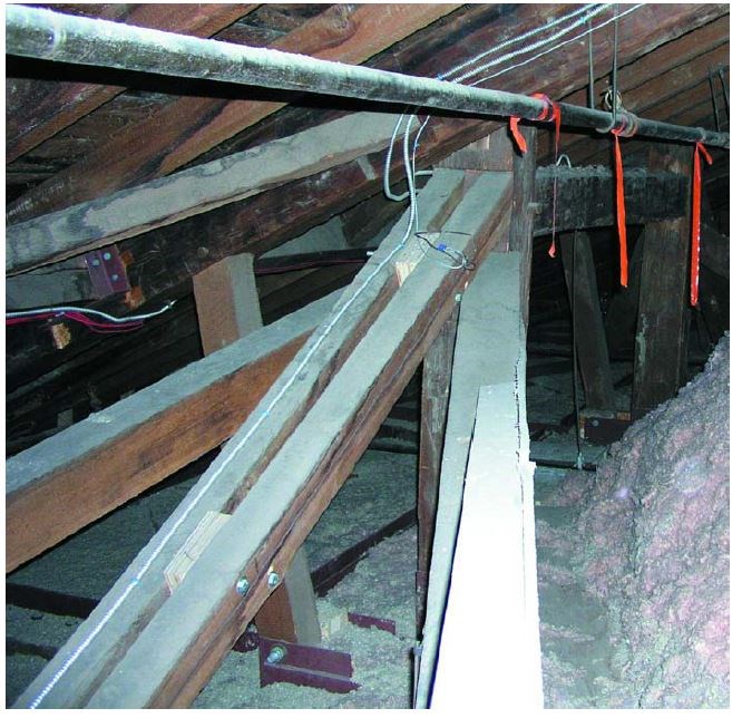
However, truncated tie beams are still found on the regular truss centers, as supporting structure for the ceiling and the dome, and these in turn are suspended from curiously framed longitudinal queenpost trusses with multiple external braces on either side of the dome (Fig. 25).
The 10x10 queenposts hang directly over these truncated tie beams, and the main braces of these trusses are quadripartite: four vertically sawn oak timbers fanning out to bear, in wedged mortises, on the bottom chords of the adjacent third and fifth truss. From each queenpost a pair of main braces drops directly to the chords of the third and fifth trusses just over their supports by the colossal columns. The efficacy of the other two braces, which drop to unsupported points on the chord, is less clear, unless they act to stabilize the lightly built truss laterally.
For a span as large as Middlebury’s, a kingpost truss without prince posts would be only marginally adequate, but the colossal columns that rise to the truss chords and the longitudinal queenpost trusses resolve any problems, and there is little sag in the roof or ceiling. —JAN LEWANDOSKI Additional research for this article was contributed by Ed Levin, Ken Rower and Jack A. Sobon.
BIBLIOGRAPHY
Andres, G., “Lavius Fillmore and the Federal Style Meeting House,”in New England Meeting House and Church: 1630–1850, ed. P. Benes,Boston, 1980.Freeman, S.A., The Congregational Church of Middlebury, Vermont,Middlebury, 1990.
Gwilt, J., The Encyclopedia of Architecture, London, 1867.
Hammond, J., “The 18th Century Church Designs of Robert Smith,”TF 73, September 2004.
Hewett, C.E., Church Carpentry, London, 1982.
—, English Cathedral and Monastic Carpentry, Chichester, 1985. Historic American Buildings Survey, Middlebury, Vermont, Vt-11.
Isham, N., The Meeting House of the First Baptist Church in Providence,Providence, 1925.
Johnson, J., Unpublished manuscript collection, University of Vermont Special Collections, Burlington, Vt.
Kelly, J.F., Early Connecticut Meeting Houses, 2 vol., N.Y., 1948. Lewandoski, J., “The Erection of Church Steeples,” TF 36, June 1995. Recueil de 239 Dessins relatif à l’Art de l’Ingénieur, École royale des Ponts et Chaussées, Paris, 1825.
