Last updated: April 7, 2025
Article
Assessment of Mechanical Scanning Sonar in the Documentation of Submerged Cultural Resources
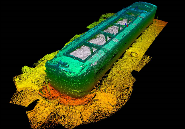
Lake Champlain Maritime Museum/Christopher Sabick and Alex Lehning
Project Title: Assessment of Mechanical Scanning Sonar in the Documentation of Submerged Cultural Resources
Organization: Lake Champlain Maritime Museum
Principal Investigators: Christopher Sabick and Alex Lehning
Date of Final Report: January 2016
Abstract
The report presents the results of a study carried out in the summer of 2012 to assess the viability of Mechanical Scanning Sonar in the documentation of submerged cultural resources. With support of the National Center for Preservation Technology and Training (NCPTT), a division of the National Park Service (NPS), and industry partner Teledyne‐Blueview, archaeologists from the Lake Champlain Maritime Museum (LCMM) carried out a detailed sonar documentation of the a shipwreck known as the Sloop Island Canal Boat (VT‐CH‐843) which sank in the Vermont waters of Lake Champlain sometime in the early twentieth century. This site had been the focus of two field seasons of traditional archaeological documentation carried out in the summers of 2002 and 2003. The fact that this vessel had been thoroughly recorded using traditional archaeological techniques allowed for a careful assessment of the results that were generated using the emerging technology of mechanical scanning sonar. Documentation using mechanical scanning sonar allows archaeologist to record the features of a submerged site with great efficiency even in low visibility environments.
List of Figures
Introduction
The report presents the results of a study carried out in the summer of 2012 to assess the viability of mechanical scanning sonar in the documentation of submerged cultural resources. With support of the National Center for Preservation Technology and Training (NCPTT), a division of the National Park Service (NPS), and industry partner Teledyne‐Blueview, archaeologists from the Lake Champlain Maritime Museum (LCMM) carried an detailed sonar documentation of the a shipwreck known as the Sloop Island Canal Boat (VT‐CH‐843) which sank in the Vermont waters of Lake Champlain sometime in the early twentieth century. This site had been the focus of two field seasons of traditional archaeological documentation carried out in the summers of 2002 and 2003. The fact that this vessel had been thoroughly recorded using traditional archaeological techniques allowed for a careful assessment of the results that were generated using the emerging technology of mechanical scanning sonar.
Lake Champlain Maritime Museum/Christopher Sabick and Alex Lehning
Project Location and Description
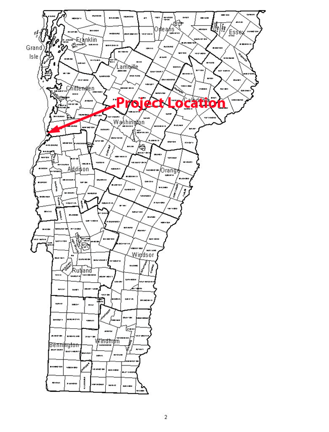
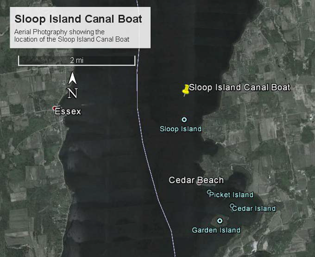
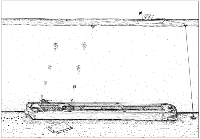
The Sloop Island Canal Boat site (VT‐CH‐843) is located in the waters of Lake Champlain and contained within Chittenden County in the Town of Charlotte, Vermont. (Figure 1 and Figure 2). The Sloop Island Canal Boat is a large wooden structure lying on an otherwise featureless bottom in nearly 90 feet (27.4m) of water. At 97 feet (29.6 m) long, 17 feet (5.2 m) wide and standing 10 feet (3.1 m) proud of the bottom the structure of the wreck is impressive (Figure 3). Its cargo capacity (98 short tons or 9800 ft2 [277.6 m2]) is roughly equivalent to two standard 40 foot (12.2 m) long tractor‐trailer containers. In 2002 and 2003, this large submerged structure received 298 research dives, most of which were devoted to recording the canal boat’s construction.
Lake Champlain Maritime Museum/Google Maps
LCMM Collection/Adam Kane
Report Organization
This report is broken down into four main sections and three appendices. Section one presents the project background and description. The second section describes the methodology employed in the research project to collect and assess the data. Section three presents the results of the project assessment. Section four presents the conclusions of the project.
Appendix 1 presents the log book entries for every sonar scan taken during the project and records the settings that were used for each. Appendix 2 contains the dive logs of the project personnel. Appendix 3 provides a Glossary of common terms used in the discussion of ships, shipwrecks, and nautical archaeology.

LCMM Collection/Chris Sabick
LCCM Collection
Methodology
The 2012 documentation of the Sloop Island Canal Boat employing the Teledyne‐BlueView mechanical scanning sonar was the first such operation carried out by Lake Champlain Maritime Museum archaeologists. For this reason the methodology employed for this project was generated as the project proceeded and through close consultation with the experts at Teledyne‐BlueView. The following section will describe the techniques employed during the Sloop Island Canal Boat survey and provide rational for the decisions that were made.
Equipment
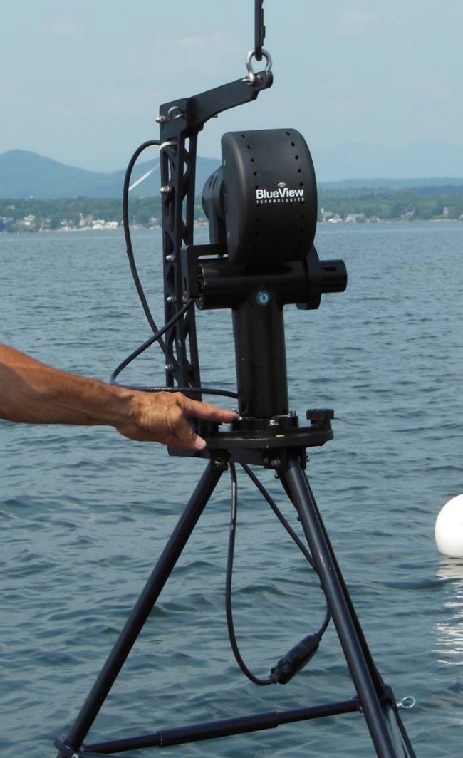
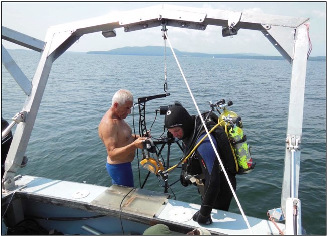
Through generous support by Teledyne‐BlueView the 2012 Sloop Island Canal Boat survey had access to a BV5000‐2250 mechanical scanning sonar unit and its associated tripod and pan and tilt unit (Figure 5). This unit was selected due to it higher resolution scanning (2.25 MHz) abilities in comparison to the BV5000‐1350 (1.35 MHz).
LCMM Collection
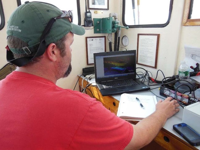
Data capture was carried out with a standard laptop computer which was running Teledyne‐BlueView’s ProScan and BlueViewer software packages.
The BlueView Survey of the Sloop Island Canal Boat was carried out from the RV Baldwin, LCMM’s research vessel. RV Baldwin is a 31 foot (9.4m) Duffy racing hull lobster boat outfitted with an hydraulic winch equipped H‐Frame and an enclosed cabin to protect sensitive equipment.
LCMM Collection
LCMM Collection
Training
In preparation for the scanning project archaeologist Christopher Sabick attended BlueView U, a four day training presented by Teledyne‐BlueView in Seattle, Washington. This course provided training on subjects ranging from basic sonar theory to practical, hands‐on, experience in deploying the scanning unit. It also included an introduction to the software and techniques needed to assemble a data point cloud created from multiple scan locations. BlueView U also allowed LCMM archaeologists to consult directly with the Teledyne‐BlueView staff on the how to approach the scanning project on the Sloop Island Canal Boat. This proved to be a very important benefit of the training program.
LCMM Collection
Pre‐Scan Infrastructure
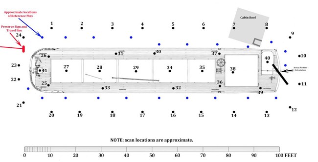
Based on the instruction presented at BlueView U and in an effort to make the scanning project as precise and efficient as possible, LCMM archaeologists spent a considerable amount of time preparing the site for work. This effort included the establishment of a three point anchoring system which allowed the RV Baldwin to be positioned directly above the wreck site each day of operations. Central positioning of the vessel in the work area was vital to ensuring that all pre‐planned scan locations could be reached with the 200 feet (61m) of cable provided with the BV5000.
LCMM Collection
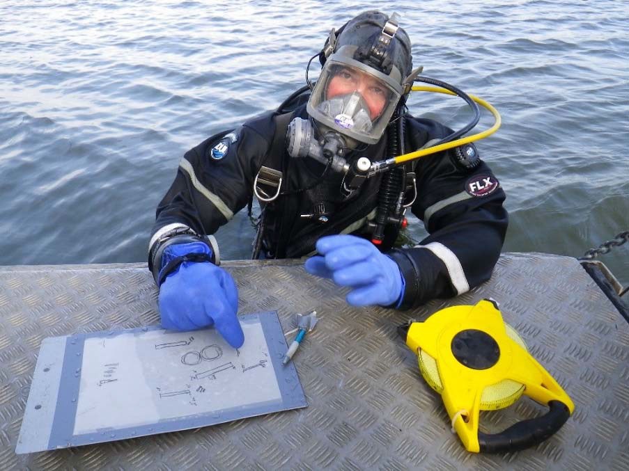
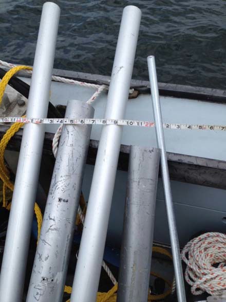
The baselines were also employed to position the registration marks between each of the scan locations and approximately 7 feet (2.13m) from the hull structure. The careful positioning of the registration marks ensured that they would appear in scans taken to either side, thus allowing for easier stitching of images in the post‐processing of the data. After the first few scans we found the reference pins hard to locate in the data. This prompted us to position future reference marks closer to the hull (4 feet [1.2m]from the structure) and favor the larger pins over the smaller. This minor shift in methodology made a considerable difference in making the reference marks readily visible in the sonar data.
Deployment of Scanner
The handling of the scanning unit, both above and below water, was a major consideration of the project planning. With the sonar head and pan and tilt unit attached to the supplied tripod the unit measured more than 4 feet (1.2m) in height and weighed approximately 25 pounds (11.3kg). The arrangement is somewhat top heavy when lifting in air but very stable when planted firmly on deck or on the lake bottom.

LCMM Collection
LCMM Collection
Once on the lake bottom the LCMM crew took a creative approach to moving the scanning unit around the site. Project Dive Master Pierre LaRocque devised a system that employed a small lift bag that was attached to the lifting arm of the scanner. A small scuba cylinder was strapped to one leg of the tripod and air from this cylinder could be added to the lift bag making the scanning unit slightly positively buoyant. In this state the unit was easy for free swimming divers to move between the preplanned scanning locations. Once at a new scan location the diver would release air from the lift bag allowing the unit to settle firmly onto the lake bottom. The use of a diver communication system greatly aided this process.
LCMM Collection
The use of a diver to position the scanning unit offered several advantages over simply lowering the unit to the bottom from the surface. Diver positioning ensured that the scanner was placed at a known location and that it was oriented properly. Proper orientation allowed the sonar operator to capture 180 degree scans, instead of 360 degree scans, thereby reducing the duration of each scanning cycle (3 minutes versus 6 minutes) and the minimizing the amount of superfluous data captured while still ensuring that the structure being scanned was in the sonar unit’s “field of vision.” Diver positioning of the scanning unit also allowed for careful placement of the tripod on the narrow deck of the canal boat and even inside the cargo hold and forecastle hatch. These locations would have been difficult, if not impossible, to achieve if the scanner had been deployed from the surface.
LCMM Collection
Post Processing
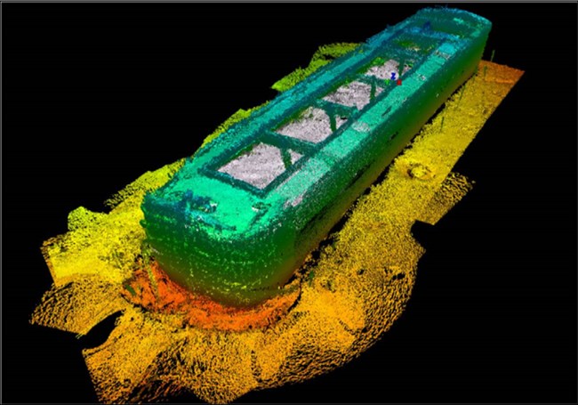
The post processing of the data that was collected by the LCMM of the Sloop Island Canal Boat was carried out by the experts at Teledyne‐BlueView. The ability to manipulate and stitch together the individual point clouds captured by the BV5000 is an additional skill set that would have required a significant amount of additional training which was beyond the scope of this project. Therefore the numerous point clouds that were generated by the scanning project were shipped to Teledyne‐BlueView, along with a wish‐list of final products. The technicians at Teledyne‐BlueView were able to generate a composite point cloud of the entire vessel at several levels of resolution, as well as numerous high‐resolution images for comparison with the documentation drawings produced from the 2002‐2003 field work. Finally the data was used to create a “fly through” movie of the point cloud that could be easily shared with the public and other researchers. This can be seen on YouTube at this link:
NOTE: The third-party video referenced below is not audio described, nor closed captioned.
Title: 3D Sonar Scan of the Sloop Island Canal Boat
URL: https://www.youtube.com/watch?v=CIzLQ_8L5g4
LCMM Collection
Assessment
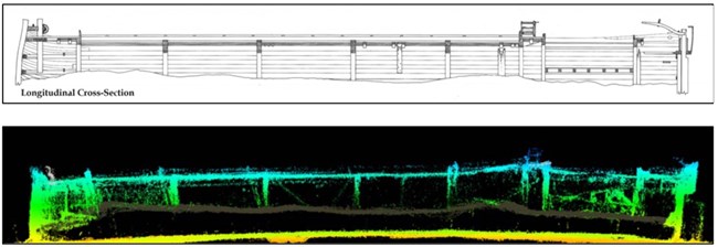
In order to gain a more complete understanding of the capabilities of the mechanical scanning sonar for documenting complex submerged cultural resources, LCMM archaeologist compared the various images created from the post‐processed sonar data with the drawings that were created from the traditional data set. In order to carry out this comparison LCMM researchers asked the technicians at Teledyne‐BlueView to create images from the sonar data that were similar to the paper drawings. The list of images includes a digital plan view, longitudinal cross‐section, two transverse cross sections and an image showing the details of the bow structure. In order to check the accuracy of the different images measurements were taken from both and compared. As the paper drawing were all done to scale, measurements were easy to acquire.
LCMM Collection
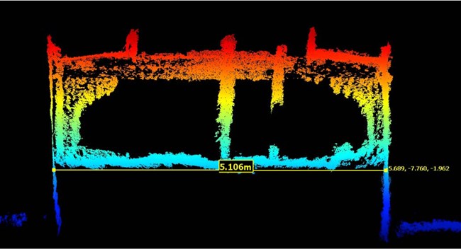
One feature of this software allows measurements to be taken between any two selected points on the image, this mechanism was used to collect the measurements for comparison (Figure 13).
Additional comparisons were made of the shapes of the structures represented by both data sets and information collected about which timbers are identifiable. A detailed discussion of these comparisons is presented in the following section of this report.
Chris Sabick, LCMM Collection
Project Results
Over the course of the three days of scanning field work the LCMM crew was able to collect 60 scans of the Canal Boat from a total of 41 locations around, on, and in the vessel remains. The assembly of all of these disparate point clouds into one comprehensive image of the entire vessel was carried out by the experts at Teledyne‐BlueView. The results were very impressive and added significantly to our understanding of the vessel and its condition on the bottom of Lake Champlain. Through a careful comparison with the drawings created from the “traditional” data set collected in 2002 and 2003 LCMM archaeologists were able to evaluate the scanning sonar system’s ability to document complex structures underwater. Conversely, the BlueView data also pointed out some flaws in that earlier data set.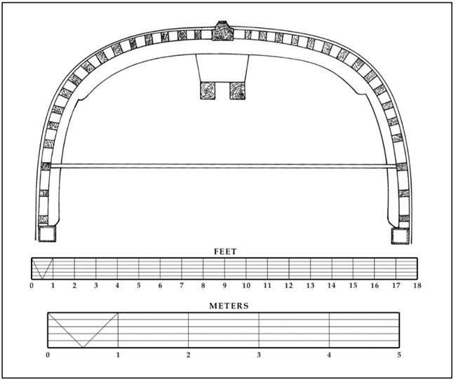
Chris Sabick, LCMM Collection
Speed of Data Collection
The speed with which a complex structure like a shipwreck can be documented with the BlueView BV5000 is certainly one of its greatest strengths. The ability to capture a significant level of detail of an entire shipwreck in just a couple of days of field work is impressive. When employed with the proper research design and realistic goals this technology can become an important part of the underwater archaeology “tool box.” The following section contains an analysis of some of the detailed drawings created from the traditionally recorded data set compared to images generated in a much shorter time by the mechanical scanning sonar.
LCMM Collection
LCMM Collection
When one compares some basic measurements taken from both the traditional data set and the digital point cloud it becomes apparent that the BlueView System has done an excellent job in scaling. The average beam measurement recorded in 2002 is 17ft (5.2m).
When captured from the point cloud using the measuring tool included in the BlueViewer software, the average beam measurement is 17 feet 1⁄2 inch (5.2m). When comparing the overall length of the Sloop Island Canal Boat, the traditional documentation gives us a length of 97 feet (29.53m), while from the point cloud the measurement is 96 feet 10 1⁄2 inches (29.52m), a difference of only 1 1⁄2 inches (3.8cm) over nearly 100 feet (30.5m).
The accuracy of measurement is also demonstrated on a smaller scale when the molded dimensions of the deck beams are compared. The measurements are 8 inches (20.3cm) in the traditional data set and in only .07 inches (.17cm) larger in the digital data, this difference can be explained by imperfections in the wood or biological growth on the wood that are discounted when taking measurements by hand.
LCMM Collection
Plan View Comparison
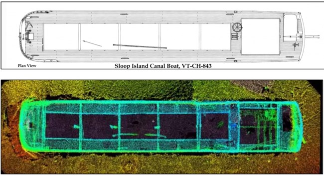
A general comparison of the plan view images generated by the two documentation techniques employed on the Sloop Island Canal Boat demonstrate the BV5000’s ability to document complex shapes, even over a large area (Figure 14). The combined BlueView point cloud has accurately recorded the overall hull shape, location of deck beams and other deck features, and has even included some structures within the cabin that were not included in the plan view pencil drawing. In fact, the point cloud image indicates that the shape of the bow was not properly recorded in the traditional documentation. A careful examination of the transition from the sides to the bow shows that the “corner” is actually a much tighter curve than is presented in the line drawing. However, the point cloud images fails to capture some of the more refined details that can be included in a traditional line drawing. For example the seams between deck planking are not visible on the point cloud image.
When one compares some basic measurements taken from both the traditional data set and the digital point cloud it becomes apparent that the BlueView System has done an excellent job in scaling. The average beam measurement recorded in 2002 is 17ft (5.2m). When captured from the point cloud using the measuring tool included in the BlueViewer software, the average beam measurement is 17 feet 1⁄2 inch (5.2m). When comparing the overall length of the Sloop Island Canal Boat, the traditional documentation gives us a length of 97 feet (29.53m), while from the point cloud the measurement is 96 feet 10 1⁄2 inches (29.52m), a difference of only 1 1⁄2 inches (3.8cm) over nearly 100 feet (30.5m). The accuracy of measurement is also demonstrated on a smaller scale when the molded dimensions of the deck beams are compared. The measurements are 8 inches (20.3cm) in the traditional data set and in only .07 inches (.17cm) larger in the digital data, this difference can be explained by imperfections in the wood or biological growth on the wood that are discounted when taking measurements by hand.
Cross‐section 4 Comparison
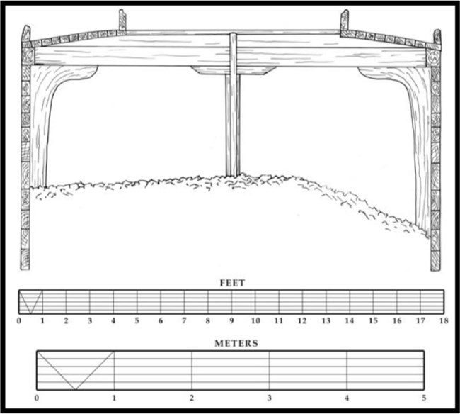
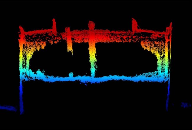
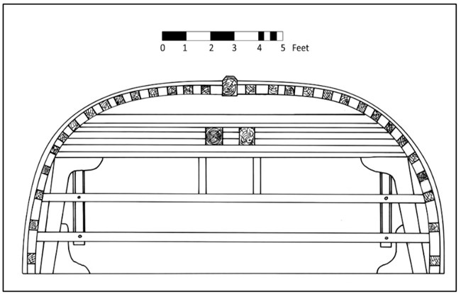
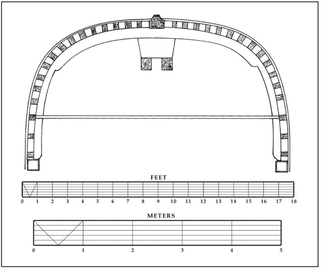
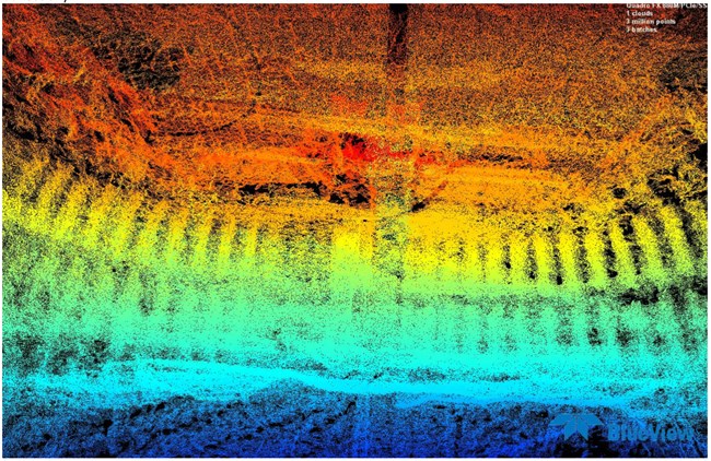
A comparison of the cross sections taken amidships of the Sloop Island Canal Boat again demonstrate that the point cloud data does an admirable job in recording the complex shapes presented at this location (Figure 15 and 16). The location of the deck beams, stanchions, hanging knees, and hatch coaming are all readily apparent. The current arrangement of the coal cargo at this section is also more accurately represented in the digital image than in the line drawing. When the documentation for the line drawing was done the LCMM team had attempted to excavate through the cargo of coal to access the bottom of the vessel. This task proved exceedingly difficult and the attempt was abandoned. Therefore the line drawing shows the disturbed coal, the sonar image shows the coal after it was back filled.
As with the plan view a comparison of measurements demonstrates that the BV‐5000 accurately captured relevant gross measurements. The beam measurements are comparable between data sets, as are the width of the cargo hatch and the height of the hatch coaming all of which demonstrate less than 1/2 inch (1.27cm) deviation.
However, the exact dimensions of the individual structural timbers and their exact shape would be difficult to extract from the digital image with any accuracy. For instance, Figure 15 shows that the athwartships deckbeam is composed of two distinct timbers, a roughly square beam with a trapezoidal timber on top of it. The combined shape of these two timbers is apparent in the sonar image (Figure 16) but it is not clear that it is two distinct structural components. Similarly, the exact dimensions of the hanging knees are hard to determine in the sonar image.
The interior structure of the forecastle area of the Sloop Island Canal Boat is quite complex and was difficult to record with both the traditional and sonar techniques. In both instances there is limited access to this portion of the boat. For a free swimming diver the hazards included an overhead environment, limited maneuvering space, and easily disturbed bottom sediments that could rapidly deteriorate visibility if disturbed. For the sonar unit it was difficult to position the scanning head to capture sufficient detail from multiple angles. This last obstacle may have been overcome by some creative deployment of the sonar head without the use of the tripod to allow more angles to be captured. However, time limitations prevented the LCMM crew from exploring these options. Therefore scans of this area could only be captured from one location (suspended below the forecastle hatch), though scans were taken at multiple angles to gather as much data as possible. Also some portions of this area were captured by the scan located in the forward most cargo hold location (scan point 27).
This is one area of structure where useful images from the sonar data were challenging to capture for presentation. The complexity of the structures and the density of data presented make it difficult to distinguish certain features when presented as screen captures for this report (Figure 19 and 20). These same structures are more readily identifiable when viewing, and manipulating, the three dimensional image with the BlueViewer software.
An examination of the images generated from the two documentation techniques shows that the point cloud data did an admirable job in capturing the vertical framing, breast hooks, and the aft faces of the bit structures in the bow but it was unable to capture the details of the complicated arrangement of timbers that were used to support the deck timbers and reinforce the curve of the bow. As mentioned above, this last issue may have been partially due to the positioning of the scanner head and the few scan angles available to the unit with the chosen method of deployment in this restricted area. As with the other comparison images, it would be challenging to take accurate measurements from the point cloud data for individual structural elements, particularly those, like the bit posts, where only one surface is visible from this scan location. In this case the lack of information may have been rectified by the ability to take additional scans of this structure from more locations.
Conclusions
The comparison of images produced with the traditional data set and those created from the point cloud data highlight some of the strengths and weaknesses of both documentation techniques. Overall, LCMM archaeologists were very pleased at the quality and quantity of data acquired at this complex site with a comparatively minimal field effort. The BlueView scanner proved very effective at capturing the shape of complex structures even over a considerable distance, and to do so with an acceptable level of accuracy. In fact, in several instances this capability pointed out areas where the traditional data set was less than accurate. The sonar data was also very effective at more accurately representing uneven or variable surfaces. This is most obvious in its ability to accurately depict the disposition of the coal cargo distributed throughout the hold of the Sloop Island Canal Boat.
Conversely the sonar imagery failed to capture the very fine level of detail that is recorded in the traditional data set. Seams between timbers, fastener patterns, and exact dimensions of many individual timbers are not identifiable in the sonar data. For example, while the surface of the deck planking was well represented in the sonar data, it is impossible to distinguish the individual deck planks that make up that surface.
One of this sonars strongest attributes is that it can achieve this level of detailed documentation even in water conditions that would make traditional recording extremely difficult, potentially inaccurate, and dangerous. Low, or zero, visibility environments are one of the most challenging dive situations in which an underwater archaeologist can work. Deployment of a mechanical scanning sonar in a situation such as this offers great potential for capturing accurate data without putting divers at risk.
In summary, the mechanical scanning sonar is a powerful tool that can capture a tremendous amount of valuable information in a relatively small amount of time. When used for the proper application and with realistic goals about the nature of the final product it will produce, this sonar technology is an extremely valuable tool in the underwater archaeologist’s toolbox. At this point in its development, mechanical scanning sonar will not replace the need for traditional documentation but can be used to make that process faster, more accurate, and more efficient. A combination of the two documentation techniques will produce the level of detail and accuracy that neither can produce on their own.
Bibliography
Kane, Adam I., Joanne M. Dennis, Scott A McLaughlin, Christopher R. Sabick. Sloop Island Canal Boat Study: Phase III Archaeological Investigation in Connection with the Environmental Remediation of the Pine Street Canal Superfund Site. Ferrisburgh: Lake Champlain Maritime Museum, 2010.
Sabick, Christopher R., Anne Wood Lessmann, and Scott A. McLaughlin. Lake Champlain
Underwater Cultural Resources Survey. Ferrisburgh: Lake Champlain Maritime Museum, 2000.
Steffy, J. Richard. Wooden Shipbuilding and the Interpretation of Shipwrecks. College Station: Texas A&M University Press, 1994.
Teledyne BlueView Inc. BV5000 User Handbook. Seattle: Teledyne BlueView, 2014.
Appendix 1: Scan Logs
Sloop Island Canal Boat Scanning Sonar Project
July 18 2012 Scan Log:
Scan Location: 1
Start Time: 11:07 am
Tilt: 0
Scan Type: 180
Sound Velocity: Scanned at 1500...should be 1455
Water Temperature: 54.3F
File Name: Jul_18_2012_110721_0
Notes: First scan of project. Off the Starboard Bow. Note Barney’s downrigger ball with Temp gauge hanging off the bow.
Scan Location: 2
Start Time: 11:13 am
Tilt: 0
Scan Type: 180
Sound Velocity: Scanned at 1500...should be 1455
Water Temperature: 54F
File Name: Jul_18_2012_111326_0
Notes: Moved Aft 10ft from Scan 1 location. We may need larger reference pins.
Scan Location: 3
Start Time: 11:18am
Tilt: 0
Scan Type: 180
Sound Velocity: scanned at 1500 should be 1455
Water Temperature: 54.2F
File Name: Jul_18_2012_111824_0
Notes: Continued aft from scan location 2 to scan location 3
Scan Location: 4
Start Time: 11:25am
Tilt: 0
Scan Type: 180
Sound Velocity: scanned at 1450 should be 1455 Water Temperature: 53.6F
File Name: Jul_18_2012_112603_0
Notes: Calibrated the temperature...almost correctly.
Scan Location: 4
Start Time: 11:37am
Tilt: ‐7
Scan Type: 180
Sound Velocity: scanned at 1450 should be 1455
Water Temperature: 52.4F
File Name: Jul_18_2012_113740_‐7
Notes: We have a little time while divers are rotated so I did a test with a down angle on the scan head just to see if it looked any better. Not really...
Scan Location: 4
Start Time: 12:46pm
Tilt: 0
Scan Type: 180
Sound Velocity: scanned at 1450 should be 1455
Water Temperature: 52.6F
File Name: Jul_18_2012_124649_0
Notes: First scan with larger reference pins located closer to wreck...roughly 3 ft. new pin on left side only...small pin on right.
Scan Location: 5
Start Time: 12:53pm
Tilt: 0
Scan Type: 180
Sound Velocity: 1450m/s
Water Temperature: 52.5F
File Name: Jul_18_2012_125343_0
Notes: Continued to move aft...new reference pins are looking good.
Scan Location: 6
Start Time: 12:59pm
Tilt: 0
Scan Type: 180
Sound Velocity: 1450
Water Temperature: 52.7F
File Name: Jul_18_2012_125933_0 Notes: Continued south
Scan Location: 6
Start Time: 1:09pm
Tilt: 0
Scan Type: 90
Sound Velocity: 1455
Water Temperature: 52.7F
File Name: Jul_18_2012_130931_0
Notes: Between divers so trying some different settings...threshold lowered to 100
Scan Location: 6
Start Time: 1:12pm
Tilt: 0
Scan Type: 90
Sound Velocity: 1455
Water Temperature: 52.7F
File Name: Jul_18_2012_131224_0
Notes: Another test...Threshold raised to 500
Scan Location: 6
Start Time: 1:12pm
Tilt: 0
Scan Type: 90
Sound Velocity: 1455
Water Temperature: 52.7F
File Name: Jul_18_2012_131224_0
Notes: Another test...Threshold raised to 500
Scan Location: 6
Start Time: 1:15pm
Tilt: 0
Scan Type: 90
Sound Velocity: 1455
Water Temperature: 52.7F
File Name: Jul_18_2012_131526_0 Notes: Another Test Threshold set to 150
Scan Location: 7
Start Time: 1:39 pm
Tilt: 0
Scan Type: 180
Sound Velocity: 1455
Water Temperature: 53.4F
File Name: Jul_18_2012_133955_0
Notes: Continuing aft decided to stick with a threshold of 150
Scan Location: 8
Start Time: 1:44pm
Tilt: 0
Scan Type: 180
Sound Velocity: 1448
Water Temperature: 52.7F
File Name: Jul_18_2012_134451_0
Notes: Arriving at the starboard stern quarter
Scan Location: 9
Start Time: 1:51 pm
Tilt: 0
Scan Type: 180
Sound Velocity: 1448
Water Temperature: 52.3F
File Name: Jul_18_2012_135104_0
Notes: Last scan of the day...starting around the corner.
July 19 2012 Scan Log:
Scan Location: 10
Start Time: 11:02 am
Tilt: 0
Scan Type: 180
Sound Velocity: 1455 m/s
Water Temperature: 54F
File Name: Jul_19_2012_110226_0
Notes: First scan of day Thursday. Off the stern about 10‐11 ft. Great shot of the stern and rudder from the stb side. PP
Scan Location: 11
Start Time: 11:08am
Tilt: 0
Scan Type: 180
Sound Velocity: 1455m/s
Water Temperature: 54F
File Name: Jul_19_2012_110817_0
Notes: Continuing around stern to port side. PP
Scan Location: 12
Start Time: 11:13am
Tilt: 0
Scan Type: 180
Sound Velocity: 1455 m/s
Water Temperature: 54F
File Name: Jul_19_2012_111306_0
Notes: Off the port stern quarter attempting to look behind the rudder. PP
Scan Location: 13
Start Time: 11:18am
Tilt: 0
Scan Type: 180
Sound Velocity: 1455m/s
Water Temperature: 54F
File Name: Jul_19_2012_111841_0
Notes: Starting on Port side scanner moved in 2 feet from designated locations as per Nicks suggestion...now about 11ft from wreck. PP
Scan Location: 14
Start Time: 12:06pm
Tilt: 0
Scan Type: 180
Sound Velocity: 1455m/s
Water Temperature: 54F
File Name: Jul_19_2012_120633_0
Notes: Ron’s first scan continuing forward on the port side of the vessel.
Scan Location: 15
Start Time: 12:10pm
Tilt: 0
Scan Type: 180
Sound Velocity: 1455m/s
Water Temperature: 54F
File Name: Jul_19_2012_121054_0
Notes: Continuing forward on the port side. Ron
Scan Location: 16
Start Time: 12:15pm
Tilt: 0
Scan Type: 180
Sound Velocity: 1455m/s
Water Temperature: 54F
File Name: Jul_19_2012_121524_0 Notes: Amidship on Port side. Ron
Scan Location: 17
Start Time: 12:19pm
Tilt: 0
Scan Type: 180
Sound Velocity: 1455m/s
Water Temperature: 54F
File Name: Jul_19_2012_121940_0 Notes:
Scan Location: 18
Start Time: 12:50pm
Tilt: 0
Scan Type: 180
Sound Velocity: 1455
Water Temperature: 54F
File Name: Jul_19_2012_125001_0
Notes: Adam’s First Scan of the day. Some tether maintenance. With the stern anchor line. Note only one post placed to the left of the scanner on this position...though it appears that you can see both posts from the last location.
Scan Location: 19
Start Time: 12:53pm
Tilt: 0
Scan Type: 180
Sound Velocity: 1455
Water Temperature: 54F
File Name: Jul_19_2012_125331_0
Note: Scan aborted due to tension on the tether.
Scan Location: 19
Start Time: 12:56pm
Tilt: 0
Scan Type: 180
Sound Velocity: 1455
Water Temperature: 54F
File Name: Jul_19_2012_125626_0
Notes: Possible Tether tension issues on this one too. But on review it looks fine
Scan Location: 20
Start Time: 1:00pm
Tilt: 0
Scan Type: 180
Sound Velocity: 1455
Water Temperature: 54F
File Name: Jul_19_2012_130048_0
Notes: Last scan on Port side before rounding the corner on the bow
Scan Location: 21
Start Time: 1:05pm
Tilt: 0
Scan Type: 180
Sound Velocity: 1455
Water Temperature: 54F
File Name: Jul_19_2012_1300456_0
Notes: Quartering shot of the bow. Excellent shot
Scan Location: 22
Start Time: 1:09pm
Tilt: 0
Scan Type: 180
Sound Velocity: 1455
Water Temperature: 54F
File Name: Jul_19_2012_130902_0
Notes: View of bow just slightly off to port facing aft. Reference pin located to the right of the scanner...to the left you can see the preserve sign and travel line. Another Great shot.
Scan Location: 23
Start Time: 2:26pm
Tilt: 0
Scan Type: 180
Sound Velocity: 1455
Water Temperature: 54F
File Name: Jul_19_2012_142631_0
Notes: PP second dive...located just to stb of stem looking aft. Excellent shot of the sign and travel line.
Scan Location: 24
Start Time: 2:31pm
Tilt: 0
Scan Type: 180
Sound Velocity: 1455
Water Temperature: 54F
File Name: Jul_19_2012_143119_0
Notes: PP little further off to stb around bow
Scan Location: 25
Start Time: 2:39pm
Tilt: ‐45
Scan Type: 360
Sound Velocity: 1455
Water Temperature: 54F
File Name: Jul_19_2012_143908_‐46
Notes: First 360 scan locate on the deck in the bow...Port side. I may have the start range set too short on this scan
Scan Location: 26
Start Time: 2:48pm
Tilt: ‐45
Scan Type: 360
Sound Velocity: 1455
Water Temperature: 54F
File Name: Jul_19_2012_144808_‐46
Notes: Same as above on Stb Bow I fiddled with the ranges a bit on this shot...stretched out the start and shortened up the stop range to 7.3
Scan Location: 27
Start Time: 2:59pm
Tilt: ‐30
Scan Type: 360 spherical
Sound Velocity: 1455
Water Temperature: 54F
File Name: Jul_19_2012_145905_‐30
Notes: Tipped slightly aft. Located atop the coal in the forward section of the cargo hatch. I’m doing a 360 spherical scan at ‐30
Scan Location: 27
Start Time: 3:17pm
Tilt: 0
Scan Type: 360 spherical
Sound Velocity: 1455
Water Temperature: 54F
File Name: Jul_19_2012_151740_0
Notes: Same location as above but at 0 tilt angle
Scan Location: 27
Start Time: 3:29pm
Tilt: ‐45
Scan Type: 360
Sound Velocity: 1455
Water Temperature: 54F
File Name: Jul_19_2012_152931_‐45
Notes: Same location again with a ‐45 down tilt
Scan Location: 28
Start Time: 3:43pm
Tilt: ‐30
Scan Type: 360 spherical
Sound Velocity: 1455
Water Temperature: 54F
File Name: Jul_19_2012_154316_‐30
Notes: Moved Aft to next bay in the cargo hold.
Scan Location: 29
Start Time: 3:52pm
Tilt: ‐30
Scan Type: 360 spherical
Sound Velocity: 1455
Water Temperature: 54F
File Name: Jul_19_2012_155249_‐30
Notes: Moved Aft to 3rd bay in the cargo hold. Last scan 0of the day
Scan Location: 30
Start Time: 10:19pm
Tilt: ‐35
Scan Type: 360
Sound Velocity: 1455
Water Temperature: 57F
File Name: Jul_20_2012_101914_‐35
Notes: First Scan of the day...Adam in the water...hoping to get good placement on the walkway along the cargo hatch. I’m trying the ‐35 down angle. Looks good...good angle
Scan Location: 31
Start Time: 10:28am?
Tilt: ‐35
Scan Type: 360
Sound Velocity: 1455
Water Temperature: 57F
File Name: Jul_20_2012_102827_‐36
Notes: Moved forward along walkway about 1 deckbeam near large cleat for this scan. Scan Aborted due to loss of power....massive boat wake knocked over the generator.
Scan Location: 31
Start Time: 10:35am
Tilt: ‐35
Scan Type: 360
Sound Velocity: 1455
Water Temperature: 57F
File Name: Jul_20_2012_103514_‐36
Notes: Redo of last scan...Adam had to leave the unit due to air limitations so I will be able to try a couple of scans at this point to try different angles. Need to adjust Sound velocity to 1482m/s.
Scan Location: 31
Start Time: 10:47am
Tilt: ‐45
Scan Type: 360
Sound Velocity: 1482
Water Temperature: 57F
File Name: Jul_20_2012_104719_‐45
Notes: Same location as above but with a ‐45 angle and adjusted sound velocity.
Scan Location: 31
Start Time: 11:10am
Tilt: ‐20
Scan Type: 360
Sound Velocity: 1482 m/s
Water Temperature: 57F
File Name: Jul_20_2012_111038_‐20
Notes: Same location as above but with a shallower angle...just messing around. Don’t think it’s a lot better...I’ll stick with ‐35.
Scan Location: 32
Start Time: 11:36 am
Tilt: ‐35
Scan Type: 360
Sound Velocity: 1482 m/s
Water Temperature: 57F
File Name: Jul_20_2012_113638‐34
Notes: Ed’s first dive with the unit. Increased the threshold to 250 to see what that does.
Scan Location: 33
Start Time: 11:46am
Tilt: ‐35
Scan Type: 360
Sound Velocity: 1482
Water Temperature: 57F
File Name: Jul_20_2012_114717_‐35 Notes: Ed’s second placement.
Scan Location: 33
Start Time: 12:06pm
Tilt: ‐20
Scan Type: 360
Sound Velocity: 1482
Water Temperature: 57:
File Name: Jul_20_2012_120621_‐21
Notes: Just running a shallow angle scan as we are between divers.
Scan Location: 34
Start Time: 12:17pm
Tilt: 0
Scan Type: 360
Sound Velocity: 1482m/s
Water Temperature: 57F
File Name: Jul_20_2012_121701_0
Notes: PPs first place of the day...in hold 2 compartments fwd of cabin hole.
Scan Location: 35
Start Time: 12:24pm
Tilt: 0
Scan Type: 360
Sound Velocity: 1482
Water Temperature: 57F
File Name: Jul_20_2012_122446_0 Notes: Next Bay Aft. PP.
Scan Location: 36
Start Time: 12:34pm
Tilt: ‐35
Scan Type: 360
Sound Velocity: 1482
Water Temperature: 57F
File Name: Jul_20_2012_123425_‐36
Notes: Located on port side of walkway with the wheel
Scan Location: 37
Start Time: 12:42
Tilt: ‐36
Scan Type: 360
Sound Velocity: 1482
Water Temperature: 57F
File Name: Jul_20_2012_124228_‐36
Notes: Located on Stb side of walkway with wheel. PP
Scan Location: 38
Start Time: 12:52pm
Tilt: ‐35
Scan Type: 360
Sound Velocity: 1482
Water Temperature: 57F
File Name: Jul_20_2012_125218_‐35
Notes: Center of cabin space...down angle scan. PP is heading up so I’ll be able to do a couple of different angles at this location.
Scan Location: 38
Start Time: 1:02pm
Tilt: 0
Scan Type: 360
Sound Velocity: 1482
Water Temperature: 57F
File Name: Jul_20_2012_130258_0
Notes: Same location as above but with 0 tilt.
Scan Location: 38
Start Time: 1:13pm
Tilt: +20
Scan Type: 360
Sound Velocity: 1482m/s
Water Temperature: 57F
File Name: Jul_20_2012_131330_21
Notes: Third scan in cabin with an up angle.
Scan Location: 39
Start Time: 1:22pm
Tilt: ‐35
Scan Type: 360
Sound Velocity: 1482m/s
Water Temperature: 57F
File Name: Jul_20_2012_132243_‐35
Notes: Port side of stern deck scanning with a down angle NOTE: This Scan is far from level due to the deck having slumped away.
Scan Location: 40
Start Time: 1:30pm
Tilt: ‐20
Scan Type: 360
Sound Velocity: 1482
Water Temperature: 57F
File Name: Jul_20_2012_1331_‐20
Notes: Booby hatch Down angle. Rons last placement so I’ll hit another scan or two while I can.
July 20 2012 Scan Log:
Scan Location: 40
Start Time: 1:40pm
Tilt: 0
Scan Type: 360
Sound Velocity: 1482m/s
Water Temperature: 57F
File Name: Jul_20_2012_134045_0
Notes: Same location in Booby but 0 tilt. Ron
Scan Location: 41
Start Time: 2:17pm
Tilt: 0
Scan Type: 360
Sound Velocity: 1482m/s
Water Temperature: 57F
File Name: Jul_20_2012_141703_0
Notes: Inverted in the Forecastle 0 scan angle.
Scan Location: 41
Start Time: 2:24pm
Tilt: +15
Scan Type: 360
Sound Velocity: 1482m/s
Water Temperature: 57F
File Name: Jul_20_2012_142540_16
Notes: Same inverted location with 15 up angle
Scan Location: 41
Start Time: 2:34pm
Tilt: ‐15
Scan Type: 360
Sound Velocity: 1482m/s
Water Temperature: 57F
File Name: Jul_20_2012_143421_‐15
Notes: Same inverted location with 15 down angle
Scan Location: 41
Start Time: 2:42pm
Tilt: ‐44
Scan Type: 360
Sound Velocity: 1482m/s
Water Temperature: 57F
File Name: Jul_20_2012_144211_‐45
Notes: Same Inverted location with a 45 down angle
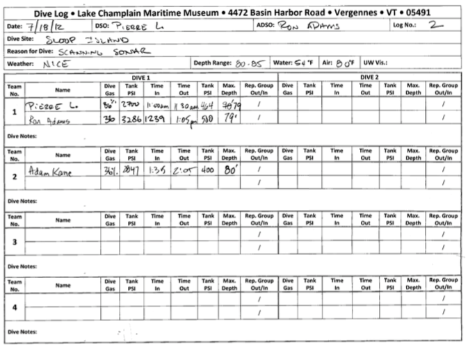
Lake Champlain Maritime Museum
| Date: 7/18/2012 | DSO: Pierre L. | ADSO: Ron Adams | LOG No.: 2 |
| Dive Site: Sloop Island |
| Reason for Dive: Scanning sonar |
| Weather: Nice | Depth Range: 80-85 | Water: 54 °F | Air: 80 °F | UW Vis.: |
| DIVE 1 | DIVE 2 |
| Team No. | Name . | Dive Gas |
Tank PSI |
Time In | Time Out | Tank PSI | Max. Depth | Rep. Group Out/In |
Dive Gas |
Tank PSI |
Time In |
Time Out |
Tank PSI |
Max. Depth |
Rep. Group Out/In |
|||
|---|---|---|---|---|---|---|---|---|---|---|---|---|---|---|---|---|---|---|
| 1 | Pierre L. | 36% | 2700 | 11:00 AM | 11:30 AM | 464 | / | |||||||||||
| Ron Adams | 36 | 3286 | 1239 | 1:05 PM | 500 | 79' | / | |||||||||||
| Dive Notes: |
| DIVE 1 | DIVE 2 |
| Team No. | Name . | Dive Gas |
Tank PSI |
Time In | Time Out | Tank PSI | Max. Depth |
Rep. Group Out/In |
Dive Gas |
Tank PSI |
Time In |
Time Out |
Tank PSI |
Max. Depth |
Rep. Group Out/In |
|||
|---|---|---|---|---|---|---|---|---|---|---|---|---|---|---|---|---|---|---|
| 2 | Adam Kane | 36% | 2847 | 1:35 | 2:05 | 400 | 80' | / | ||||||||||
| / | ||||||||||||||||||
| Dive Notes: |
| DIVE 1 | DIVE 2 |
| Team No. | Name . | Dive Gas |
Tank PSI |
Time In | Time Out | Max. Depth |
Rep. Group Out/In |
Dive Gas |
Tank PSI |
Time In |
Time Out |
Tank PSI |
Max. Depth |
Rep. Group Out/In |
|||
|---|---|---|---|---|---|---|---|---|---|---|---|---|---|---|---|---|---|
| 3 | / | ||||||||||||||||
| / | |||||||||||||||||
| Dive Notes: |
| DIVE 1 | DIVE 2 |
| Team No. | Name . | Dive Gas |
Tank PSI |
Time In | Time Out | Max. Depth |
Rep. Group Out/In |
Dive Gas |
Tank PSI |
Time In |
Time Out |
Tank PSI |
Max. Depth |
Rep. Group Out/In |
|||
|---|---|---|---|---|---|---|---|---|---|---|---|---|---|---|---|---|---|
| 4 | / | ||||||||||||||||
| / | |||||||||||||||||
| Dive Notes: |
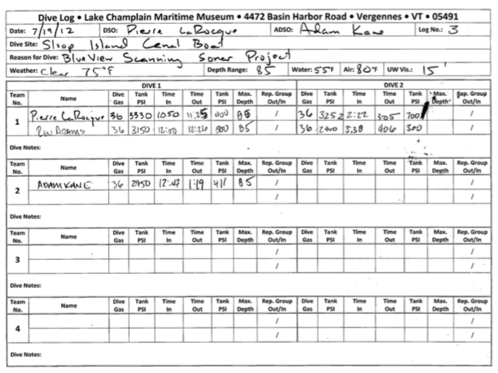
Lake Champlain Maritime Museum
| Date: 7/19/2012 | DSO: Pierre LaRocque | ADSO: Adam Kane | LOG No.: 2 |
| Dive Site: Sloop Island Canal Boat |
| Reason for Dive: BlueView Scanning Sonar Project |
| Weather: Clear 75°F | Depth Range: 85 | Water: 55 °F | Air: 80 °F | UW Vis.: 15' |
| DIVE 1 | DIVE 2 |
| Team No. | Name . | Dive Gas |
Tank PSI |
Time In | Time Out | Tank PSI | Max. Depth | Rep. Group Out/In |
Dive Gas |
Tank PSI |
Time In |
Time Out |
Tank PSI |
Max. Depth |
Rep. Group Out/In |
|||
|---|---|---|---|---|---|---|---|---|---|---|---|---|---|---|---|---|---|---|
| 1 | Pierre LaRoque | 36% | 3330 | 1050 | 11:25 | 400 | 36 | 3252 | 2:22 | 305 | 700 | / | ||||||
| Ron Adams | 36 | 3286 | 1200 | 1226 | 500 | 85' | 36 | 2400 | 3:38 | 406 | 300 | / | ||||||
| Dive Notes: |
| DIVE 1 | DIVE 2 |
| Team No. | Name . | Dive Gas |
Tank PSI |
Time In | Time Out | Tank PSI | Max. Depth |
Rep. Group Out/In |
Dive Gas |
Tank PSI |
Time In |
Time Out |
Tank PSI |
Max. Depth |
Rep. Group Out/In |
|||
|---|---|---|---|---|---|---|---|---|---|---|---|---|---|---|---|---|---|---|
| 2 | Adam Kane | 36 | 2950 | 12:47 | 1:19 | 411 | 85 | / | ||||||||||
| / | ||||||||||||||||||
| Dive Notes: |
| DIVE 1 | DIVE 2 |
| Team No. | Name . | Dive Gas |
Tank PSI |
Time In | Time Out | Max. Depth |
Rep. Group Out/In |
Dive Gas |
Tank PSI |
Time In |
Time Out |
Tank PSI |
Max. Depth |
Rep. Group Out/In |
|||
|---|---|---|---|---|---|---|---|---|---|---|---|---|---|---|---|---|---|
| 3 | / | ||||||||||||||||
| / | |||||||||||||||||
| Dive Notes: |
| DIVE 1 | DIVE 2 |
| Team No. | Name . | Dive Gas |
Tank PSI |
Time In | Time Out | Max. Depth |
Rep. Group Out/In |
Dive Gas |
Tank PSI |
Time In |
Time Out |
Tank PSI |
Max. Depth |
Rep. Group Out/In |
|||
|---|---|---|---|---|---|---|---|---|---|---|---|---|---|---|---|---|---|
| 4 | / | ||||||||||||||||
| / | |||||||||||||||||
| Dive Notes: |
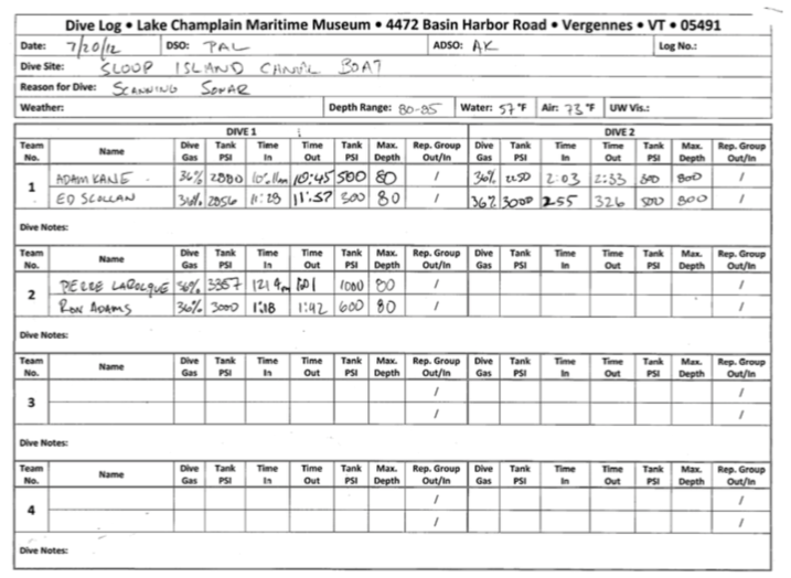
Lake Champlain Maritime Museum
| Date: 7/20/2012 | DSO: PAL | ADSO: AK | LOG No.: |
| Dive Site: Sloop Island Canal Boat |
| Reason for Dive: Scanning Sonar |
| Weather: | Depth Range: 80-85 | Water: 57 °F | Air: 73 °F | UW Vis.: |
| DIVE 1 | DIVE 2 |
| Team No. | Name . | Dive Gas |
Tank PSI |
Time In | Time Out | Tank PSI | Max. Depth | Rep. Group Out/In |
Dive Gas |
Tank PSI |
Time In |
Time Out |
Tank PSI |
Max. Depth |
Rep. Group Out/In |
|||
|---|---|---|---|---|---|---|---|---|---|---|---|---|---|---|---|---|---|---|
| 1 | Adam Kane | 36% | 2880 | 10:11 AM | 10:45 | 500 | 80 | 36% | 2250 | 2:03 | 2:33 | 600 | 800 | / | ||||
| Ed Scollan | 36% | 2856 | 11:28 | 11:57 | 300 | 80 | 36% | 3000 | 2:55 | 3:23 | 500 | 800 | / | |||||
| Dive Notes: |
| DIVE 1 | DIVE 2 |
| Team No. | Name . | Dive Gas |
Tank PSI |
Time In | Time Out | Tank PSI | Max. Depth |
Rep. Group Out/In |
Dive Gas |
Tank PSI |
Time In |
Time Out |
Tank PSI |
Max. Depth |
Rep. Group Out/In |
|||
|---|---|---|---|---|---|---|---|---|---|---|---|---|---|---|---|---|---|---|
| 2 | Pierre LaRoque | 36% | 3357 | 1214 | 101 | 1000 | 80 | / | ||||||||||
| Ron Adams | 36% | 3000 | 118 | 142 | 600 | 80 | / | |||||||||||
| Dive Notes: |
| DIVE 1 | DIVE 2 |
| Team No. | Name . | Dive Gas |
Tank PSI |
Time In | Time Out | Max. Depth |
Rep. Group Out/In |
Dive Gas |
Tank PSI |
Time In |
Time Out |
Tank PSI |
Max. Depth |
Rep. Group Out/In |
|||
|---|---|---|---|---|---|---|---|---|---|---|---|---|---|---|---|---|---|
| 3 | / | ||||||||||||||||
| / | |||||||||||||||||
| Dive Notes: |
| DIVE 1 | DIVE 2 |
| Team No. | Name . | Dive Gas |
Tank PSI |
Time In | Time Out | Max. Depth |
Rep. Group Out/In |
Dive Gas |
Tank PSI |
Time In |
Time Out |
Tank PSI |
Max. Depth |
Rep. Group Out/In |
|||
|---|---|---|---|---|---|---|---|---|---|---|---|---|---|---|---|---|---|
| 4 | / | ||||||||||||||||
| / | |||||||||||||||||
| Dive Notes: |
Appendix 3: Glossary
Aft Near or at the stern of a vessel.
Amidships The middle of a vessel.
Archaeological Site Locations where signs of human activity are found.
Archaeology A sub‐discipline of anthropology involving the study of the human past through its material remains.
Artifact Any object used or manufactured by humans.
Athwartships From one side of a ship to the other.
Barge A large, unpowered, generally flat‐bottomed boat towed by other craft and used as a freight‐hauler or work platform.
Bateau (plural bateaux) A lightly built, flat‐bottomed, double‐ended boat. Bathymetry The measurement of the depth of bodies of water.
Beam A dimension measured from side to side of a vessel.
Bedrock A mining term for the unweathered rock below the soil.
Bilge The lowest point of a vessel’s interior hull.
Bilge Stringer A fore and aft timber located in the bottom of the hull that lends longitudinal strength to the hull and keeps the frames in line.
Bitts Strong wooden or metal uprights used for securing heavy ropes such as anchor cables.
Boat An open vessel, usually small and without decks, intended for use in sheltered water.
Bollard Short thick post of wood or iron (often mounted in pairs) used for securing mooring ropes, springs, or hawsers.
Bolt A fastener consisting of a threaded rod with a head at one end, designed to be inserted through a hole in assembled parts and secured by a mated nut that is tightened by a wrench.
Boom Spar used to stretch out the foot of a sail.
Bottom Planking In an edge‐fastened vessel the planking that covers the flat bottom of the vessel,normally oriented transversely.
Bow The forward end of a vessel.
Bowsprit A spar projecting forward from the bow.
Breadth The measurement of a ship’s width.
Breakwater A structure, usually made of stone or concrete, built to create a harbor or improve an existing one.
Breast Hook A large, horizontal knee fixed to the sides and stem to reinforce and hold them together.
Bulwark The side of a vessel above the its upper deck.
Bulkhead Vertical Partition between two decks of a ship, running either lengthwise or across, forming and separating different compartments.
Cabin The living quarters of a vessel.
Canal A manmade waterway or artificially improved river used for navigation.
Canal Boat A boxy vessel designed to travel in a canal system. The vessel has no means of propulsion and must be towed or pushed by another vessel or animal.
Caprail A timber attached to the top of a vessels frames.
Cargo hatch A deck opening providing access to stow cargo below.
Causeway A raised roadway across water or mashland.
Ceiling The internal planks of a vessel.
Chine log A longitudinal timber at the angular junction of the side and bottom of a flat‐bottomed vessel.
Chock Wooden wedge used to prevent other structural members from moving.
Clamp A thick ceiling strake used to provide longitudinal support.
Cleat A T‐shaped rigging fitting to which a vessels lines are attached.
Coaming The raised lip with which openings in the deck such as hatchways are framed to prevent water on deck from running into the hold.
Cocked Hat Triangular wooden block used to brace the floors and futtocks where the bottom of the hull meets the sides.
Cultural Resource A nonrenewable historical resource such as archaeological sites, artifacts, and standing structures.
Deck A platform extending horizontally from one side of a ship to the other.
Decking The individual timbers that form the floor of the deck.
Deck beam A timber mounted across a vessel from side to side to support the vessel’s deck and provide lateral strength.
Derrick Form of crane used to hoist cargo or their weights. It consists of a swinging boom supported by a topping lift and controlled sideways by guys.
Diagonal Bracing Angled bracing in the hull of a vessel used to resist fore‐and‐aft or athwarships distortion.
Draft The depth of a vessel’s keel below the waterline when the vessel is loaded.
Drift bolt A cylindrical iron rod used to fasten ship timbers together; usually headed on one end slightly larger in diameter than the hole into which it is driven.
Edge‐fastened A shipbuilding technique used to attach the hull planks of a vessel together. The planks are set edge to edge and a hole drilled through them. Large iron bolts are driven through the planks to hold them together.
Fairlead A deck fixture used to lead a rope in a required direction.
Fender Timber designed to absorb the force from impacts with vessels or warfs. Floor Timber A frame timber that crosses the keel and spans the bottom of a vessel. Fore Located at the front of a vessel.Fore‐and‐Aft From stem to stern, from front to back, oriented parallel to the keel.
Frame A transverse timber or group of timbers that creates the skeleton of a vessel and to which the hull planking and ceiling are fastened.
Futtock A frame timber that continues where the floor timber leaves off and continues up the side of a vessel.
Gudgeon Device used to attach the rudder to the boat so that it can swing freely
Gunwale The timber above the sheer strake.
Hanging knee A vertical L‐shaped timber attached to the underside of a beam and the side of a vessel; used to connect and reinforce the junction of a deck beam with the side of the vessel.
Harbor A safe anchorage, protected from most storms; may be natural or manmade; a place for docking and loading.
Hatch A deck opening in a vessel providing access to the space below.
Historic The period after the appearance of written records for a given region.
Hold The lower interior part of a ship in which cargo is stored.
Hull The structural body of a vessel, not including the superstructure, masts or rigging.
Hull Plank A thick board used to create the outer shell of a hull.
Inboard Toward the center of the vessel.
Keel The main longitudinal timber upon which the framework or skeleton of a hull is mounted; the backbone of a hull.
Keelson An internal longitudinal timber, fastened on top of the frames above the keel for additional strength.
Knee An L‐shaped timber used to strengthen the junction of two surfaces on different planes.
Lighter A type of barge used to carry goods and equipment.
Longitudinal timber A long timber that runs parallel with the length of a vessel.
Magnetometer A scientific instrument used to measure the strength and/or direction of the magnetic field in the vicinity of the instrument. In archaeology this is used to identify metal objects.
Mast A large wooden pole that supports the sails of a vessel.
Mooring A permanent placement of an anchor, anchor chain, shackles and buoy necessary to anchor a vessel.
Mortise A cavity cut into a timber to receive a tenon.
Moulded Dimension The measurement of depth of a timber as seen in a cross‐section view of a vessel.
Mud line The intersection of a shipwreck’s hull with the bottom’s surface.
Naphtha Launch A small vessel that ran on the naphtha engine which did not use steam, but instead forms of gasoline and vapor.
Outboard Outside or away from the center of a vessel’s hull. Plank A thick board used as sheathing on a vessel.
Plank‐on‐Frame A shipbuilding technique, also commonly known as carvel built. Vessels of this type have planking running fore and aft with the planking laid edge to edge.
Port The left side of a vessel when facing forward.
Primary Source An artifact, document, or individual that provides information based on personal observations. A firsthand account.
Provenience The original location of an object, in reference to artifacts it is the exact location in which they were found.
Rabbet A concavity in the keel or chine log into which the planking is fit.
Rake The projection of a ship, at stem or stern, beyond the ends of the keel.
Rake timber Timber that acts as framing the raked end of a scow.
Rider Interior frame mounted inside a ship’s hold and bolted to other structural elements to strengthen the ship’s structure.
Rigging The hardware and equipment that support and control the spars and sails of a vessel.
Rigging block A wooden pulley used to operate a vessel’s spars and sails.
Room and Space The distance between the moulding edges of two adjoining frames.
Rub Plate A metal band placed on the forward end of the stem and bottom of the keelson to protect the underlying wood.
Rubwale See Rub Strake
Rub StrakeA rail on the outside of the hull of a boat to protect the hull from rubbing against piles, docks, and other objects
Rudderpost A vertical timber in the stern of the vessel to which the rudder is attached
Scarf An overlapping joint to connect two timbers or planks without increasing their dimensions.
Schooner A fore‐and‐aft‐rigged sailing vessel with two or more masts.
Scow Flat bottomed watercraft, normally rectangular in cross‐section with outward sloping ends.
Secondary source An individual's description and interpretation of a historical event recorded at a different time and place. A secondhand account.
Sheer strake The top strake, or plank, of a wooden vessel next below the gunwale.
Sided dimension The measurement of width of a timber as seen in a plan view of a vessel.
Sloop A single‐masted, fore‐and‐aft‐rigged sail boat.
Spar A pole used to help support the sail of a vessel.
Spike A large nail.
Spud Posts found on some barges which are lowered from the barge and pushed into the waterway floor to anchor the vessel in place.
Stanchion An upright supporting post.
Standing Knee A vertical L‐shaped timber attached to the top of a deck beam, or decking; used to connect and reinforce the junction of a deck beam with the side of the vessel.
Starboard The right side of a vessel when facing forward. Steamboat A vessel propelled by a steam engine. Steamer A vessel propelled by a steam engine.
Stern The after end of a vessel.
Strake A continuous line of planks, running bow to stern.
Stringer A longitudinal timber fixed to the inside surface of the frames of a vessel to provide it with greater strength fore‐and‐aft.
Tenon A projection on a timber which fits into a mortise.
Tiller A handle attached to the rudderpost to steer a vessel.
Timber In a general context, all wooden hull members; specially those that form the framework or skeleton of the hull.
Top Log Longitudinally oriented timber which runs on top of the futtocks.
Towfish The torpedo‐shaped unit that houses the transmitter and receiver of a side scan sonar and is usually towed behind a vessel.
Transverse Describes a component of a ship that runs side to side, not fore and aft. Underwater archaeology The archaeological study of underwater cultural resources.
Underwater cultural resource A nonrenewable historical resource that partially or entirely lies below water, such as submerged prehistoric archaeological sites, artifacts, bridges, piers, wharfs and shipwrecks.
Vessel A watercraft, larger than a rowboat, designed to navigate on open water.
Wale A thick strake of planking located along the side of a vessel for the purpose of stiffening the outer hull.
Waterline The intersection of the vessel’s hull and the water’s surface. Wharf A structure, parallel to the shore, for docking vessels.
