|
Gateways to Commerce: The U.S. Army Corps of Engineers' 9-Foot Channel Project on the Upper Mississippi River |

|
CHAPTER X
The Locks and Dams—and Those Who Built Them (continued)
The Rock Island District
The Rock Island District supervised the construction of Locks and Dams Nos.: 11, 12, 13, 14, 15, 16, 17, 18, 19, 20, 21, and 22. With the exception of Lock No. 19, all of the Rock Island District structures were constructed as part of the original 9-Foot Channel Project. The Corps of Engineers brought Lock No. 19, which includes the Keokuk and Hamilton Water Power Company dam and power plant, into its mature, 9-foot channel configuration in 1957.
Major Charles L. Hall, the same engineer who had conducted the initial, unfavorable, feasibility study of the 9-Foot Channel Project, was District Engineer of the Rock Island District at the beginning of the project. Six months after the project was signed into effect, Major Glen E. Edgerton replaced Hall, who left to teach at West Point. Major Edgerton served as District Engineer of the Rock Island District from December 1930 until August 1933. Prior to his Rock Island District appointment, Edgerton was Chief Engineer of the Federal Power Commission and a member of the Isthmian Canal Commission during the construction of the Panama Canal. These experiences served him well in his task of transforming the Rock Island District into a modern organization capable of handling the complex 9-Foot Channel Project. [17]

|
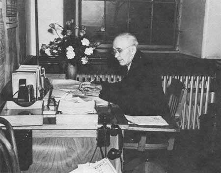
| Rock Island District Office of the U.S. Army Corps of Engineers, Clock Tower Building, June 1934. (U. S. Army Corps of Engineers, Rock Island District) |
In order to build the 9-foot channel, the Rock Island District did not need a greatly expanded engineering staff. Since 1920, Richard A. Monroe had served as Principal Civilian Assistant to the District Engineer, providing technical leadership continuity in the Rock Island District. In November 1929, shortly after the UMVD was created, Monroe became the district's Senior Engineer.
While Monroe concentrated on the district's operational issues, Herbert G. McCormick did most of the actual engineering design work. McCormick had transferred into the Rock Island District in April 1930, after more than 20 years service with the Corps on the Ohio and Lower Mississippi Rivers. On the Ohio River project, McCormick was nationally recognized for his use of a plan to place concrete through chutes from a movable concrete mixer mounted on rails. [18]
|
| Richard A. Monroe. (U.S. Army Corps of Engineers, Rock Island District) |
In August 1933, Major Edgerton completed his 3-year tour of duty as Rock Island District Engineer. The 1933 decentralization of the 9-Foot Channel Project had made the job of District Engineer a much more important position, and Captain John M. Silkman served as Acting District Engineer until a suitably capable and illustrious officer became available to replace Edgerton. Major Raymond A. Wheeler, who graduated fifth in the West Point Class of 1911, was that up-and-coming officer. Wheeler, who later became Chief of Engineers, served as District Engineer from September 1933 until October 1935, at which time he became Chief Regional Administrator of the Works Progress Administration (WPA). Major Earl E. Gesler replaced Wheeler. [19]

|
| Herbert G. McCormick. (U.S. Army Corps of Engineers, Rock Island District) |
The Rock Island District staff was also enlarged after the 1933 decentralization. Carelton E. Kelley transferred to Rock Island from the Chicago District office to become the first District Counsel and Chief of the Real Estate Division, a position he held until 1968. The district also enlarged its contract administration and construction supervision staffs. Within just a few months after the decentralization, the Rock Island District had to solicit and evaluate bids, select general contractors, and award six major project contracts. For contract purposes, each lock and each dam constituted a separate project, as did the power, control, and lighting of each lock and dam system. J.B. Alexander, the senior engineer in charge of the construction office, clearly had his hands full. In 1936, John Peil, who supervised the on-site construction of Lock and Dams No. 15 and 20, became head of the district's construction section. By the time Peil arrived in Rock Island, the district had 10 lock and dam complexes under simultaneous construction. Robert E. Clevenstine, who had also worked on site No. 20, followed Peil to the Rock Island District office, where he assumed responsibility for estimating and construction contract administration. [20]
The Rock Island District also reorganized and greatly enlarged its engineering staff after the decentralization. Monroe and McCormick remained with the district. However, after Lock and Dam No. 15 went on line in 1934, Monroe took over the primary responsibility for the operation of the facilities. Captain Silkman was in charge of the engineering division when the district assumed its new responsibilities in 1933. He was succeeded by Captain R.E. Coughlin and then Captain Henry Berbert.
Following the reorganization, Edwin E. Abbott transferred to the Rock Island District from the St. Louis UMVD design team. Taking over as chief civilian assistant, Abbott signed the contract drawings for the 10 locks, 11 dams, and 3 central control stations designed by the Rock Island District between 1933 and 1936. As early as the summer of 1933, Abbott had approximately 200 draftsmen assisting him in the production of these drawings. James Reeves and Edwin Franzen supervised the overall design of the dams, while Frank W. Ashton designed the dam gates. [21]
Lock and Dam No. 11
Date of Construction: 1934-1937
Location: Dubuque, Iowa
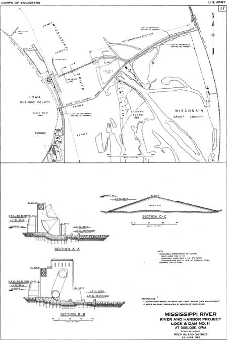
General Setting: The site borders on the northern edge of Dubuque, and is 583 miles above the confluence of the Ohio and Mississippi Rivers. Eagle Point Park occupies the high ground on the bluff above the lock and dam. A complex of islands and sloughs extends three-quarters of the way across the river from the Wisconsin shore. The Upper Mississippi River Wildlife and Fish Refuge occupies the land adjacent to the Wisconsin shore, both upstream and downstream from the dam.
Dam: The movable dam has 13 submersible Tainter gates, 20 feet high and 60 feet long; and 3 submersible roller gates, 20 feet high and 100 feet long. The roller gates submerge 8 feet. The dam system also includes a 3,540-foot long, curved, non-overflow, earth and sand-filled dike.
Lock: Lock dimensions are the standard 110 by 600 feet, with additional footings for an auxiliary lock of standard dimensions. Lock lift is 11 feet. Normal upper pool elevation is 603.0; approximately 19 feet above the tail waters below the dam at low water. When both pools are at their normal elevation, the difference is reduced to 11 feet or less.
History/Significance: Lock and Dam No. 11 was scheduled to be above Sprecht's Ferry, Iowa, but in 1933 was relocated to Dubuque. The acute unemployment in Dubuque led the government to begin construction on this complex before many other group "C" projects in the Rock Island District. Dams Nos. 11 and 18 were designed concurrently, and were the first dams in the district to employ submersible, elliptical Tainter gates. They were also the first two dams in the district to use submersible roller gates. During the peak of construction, the complex, which cost $6,655,000, employed 901 people.
General Contractors:
Lock: Warner Construction Company, Chicago, Illinois
Dam: Maxon Construction Company, Inc., Dayton, Ohio [22]
|
| Site Plan, Lock and Dam No. 11. (click on image for a PDF version) |
Lock and Dam No. 12
Date of Construction: 1934-1938
Location: Bellevue, Iowa
General Setting: Lock and Dam No. 12 is 556.7 miles above the confluence of the Ohio and Mississippi Rivers. The complex stretches across the river at a point where the bluffs on the Iowa side are very close to the river; a complex of islands and sloughs extends nearly three-quarters of the way across the river from the Illinois side. Bellevue State Park occupies the high ground on the Iowa side, while the urbanized area of Bellevue extends to the government-owned property on the flat land below the bluff. The Savannah Army Depot occupies the islands, slough, and small flat bottom areas on the Illinois side.
Dam: The movable dam consists of 7 submersible Tainter gates, 20 feet high and 64 feet long; and 3 submersible roller gates, 20 feet high and 100 feet long. The dam system also includes two, non-overflow, earth and sand-filled dikes; two transitional dikes; and a concrete-covered, ogee spillway, submersible earth and sand-filled dike. The foundation is set in sand, gravel, and silt.
Lock: Lock dimensions are the standard 110 by 600 feet, with additional footings for an auxiliary lock of standard dimensions. Lock lift is 9 feet. Normal upper pool elevation is 592 feet, approximately 15 feet above the tail waters below the dam at low water. When both pools are at their normal elevation, the difference is reduced to 9 feet or less.
History/Significance: The lock and dam elements of the complex were completed at a cost of $5,621,000. During the peak of construction, a maximum of 1,217 men were employed at one time.
General Contractors:
Lock: James Stewart Corporation, Chicago, Illinois
Dam: Wamer Construction Company, Chicago, Illinois [23]
|
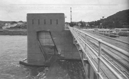
| Roller Gate, Dam No. 12. (Peter A. Rathbun) |
|
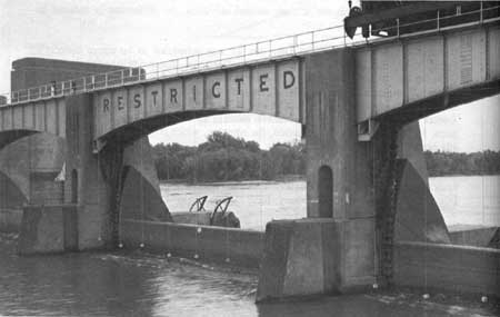
| Tainter Gate, Dam No. 12. (Peter A. Rathbun) |
Lock and Dam No. 13
Date of Construction: 1935-1939
Location: Above Clinton, Iowa
General Setting: Lock and Dam No. 13 is 522.5 miles above the confluence of the Ohio and Mississippi Rivers. The complex stretches across the river at a point where the bluffs on the Iowa side are very close to the river; islands and chutes dot the river beneath the bluffs. Eagle Point Nature Center occupies the high bluff immediately above the lock and dam. A dense group of sloughs and islands extend out from the Illinois shore.
Dam: The movable dam consists of 10 submersible Tainter gates, 20 feet high and 64 feet long; and 3 submersible roller gates, 20 feet high and 100 feet long. The Tainter gates are elliptical. The dam system also includes three non-overflow earth and sand-filled dikes; two transitional dikes; and a submersible earth and sand-filled dike.
Lock: Standard dimensions of 110 by 600 feet, with additional footings for an auxiliary lock of standard dimensions. Lock lift is 11 feet. Normal upper pool elevation is 583 feet, about 17 feet above the tail waters below the dam at low water. When both pools are at their normal elevation, the difference is reduced to 11 feet or less.
History/Significance: Locks and Dams Nos. 13, 14, and 17 were designed and built concurrently. The site for Lock and Dam No. 13 was inaccessible from the nearest highway. As a result, the general contractor constructed a dike road to the site through the sloughs, islands, and marshy bottom lands of the Illinois shore. A ferry had to be operated during the construction of the dam and central control station. It was also necessary to divert Johnson Creek so that it entered the river downstream from the lock site. The lock and dam elements of the complex were completed at a cost of $8,276,000.
General Contractors:
Lock and Dam: McCarthy Improvement Company, Davenport, Iowa [24]
|
| Lock and Dam No. 13. (Peter A. Rathbun) |

|
| Site Plan, Lock and Dam No. 13. (U.S. Army Corps of Engineers, Rock Island District) (click on image for a PDF version) |
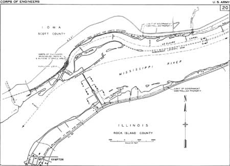
Lock and Dam No. 14
Date of Construction: 1935-1940
Location: Below Le Claire, Iowa
General Setting: Lock and Dam No. 14 is located 4 miles below Le Claire, and 493.3 miles above the confluence of the Ohio and Mississippi Rivers. The site is also 3.6 miles below the head of the notorious, rock-bedded, Rock Island Rapids. The Le Claire Lock and the remains of the Le Claire Lateral Canal, built in 1921-1924 to bypass this treacherous stretch of river, are located along the Iowa shore.
Dam: The movable dam has 13 non-submersible Tainter gates, 20 feet high and 60 feet long; and 4 submersible roller gates, 20 feet high and 100 feet long. The dam system also includes an earth and sand-filled dike.
Lock: The main lock's dimensions are the standard 110 by 600 feet. Lock lift is 11 feet. Normal upper pool elevation is 572 feet, about 15 feet above the tail waters of the dam at low water. When both pools are at their normal elevation, the difference is reduced to 11 feet or less. The dimensions of the Le Claire Lock, which is used as an auxiliary lock, are 80 by 320 feet, with a low water depth of 8 feet at the upper sill and 7 feet at the lower sill.
History/Significance: The Corps built the oldest elements of this complex between 1921 and 1924 during the 6-foot channel project. As part of that channelization, the Corps built a longitudinal dam parallelling the Iowa shore from the head of the Rock Island Rapids at Le Claire, to the head of Smith's Island. The dam formed the riverward wall of the Le Claire Canal, by which vessels could bypass the rapids. The Iowa shore served as the canal's landwall. Most of the longitudinal dam was submerged when Dam No. 14 was built; however, a portion of the original canal near the dam is still used as a mooring and storage site. The 9-foot channel lock and dam elements of the complex were built at a cost of $5,472,000.
General Contractors:
Lock and Dam: Central Engineering Company, Davenport, Iowa [25]
|
| Site Plan, Lock and Dam No. 14. (U.S. Army Corps of Engineers, Rock Island District) (click on image for a PDF version) |

|
| Aerial view of Lock and Dam No. 14. (U.S. Army Corps of Engineers, Rock Island District) |
Lock and Dam No. 15
Date of Construction: 1931-1934
Location: Rock Island and Moline, Illinois; and Davenport and Bettendorf, Iowa
General Setting: In the heart of the Quad Cities, Lock and Dam No. 15 stretches across the Upper Mississippi at one of its narrowest points, a point which is also at the foot of the Rock Island Rapids. The complex extends from the northwest tip of the U.S. Army's Arsenal Island on the Illinois side, to a small area of flat bottom land on the Iowa side. A highway and railroad bridge, joining Davenport and Rock Island, spans the site.
Dam: The movable dam has 11 non-submersible roller gates, each 100 feet long. Nine of the gates have 19-foot 4-inch diameters; 2 of the gates have 16-foot 2-inch diameters.
Lock: Standard dimensions of 110 by 600 feet; the auxiliary lock is 110 by 360 feet. Lift on both locks is 16 feet. Normal upper pool elevation is 561.0.
History/Significance: Lock and Dam No. 15 was the first 9-Foot Channel Project complex, and served as a prototype for the whole system. Still, Dam No. 15 is unusual among the project structures. It is composed entirely of roller gates, employs only non-submersible roller gates, has roller gates of differing sizes, contains non-standard length roller gates, is not at a right angle to the river, includes no earthen embankment dike section, incorporates a power plant that generates the electricity used to operate its gates and valves, and utilizes an open truss service bridge with a bulkhead lifting crane on its lower chord. The complex is also unusual in that the intermediate wall of the locks encases the swing span of a bridge. The lock and dam elements were completed at a cost of approximately $7,480,000.
General Contractors:
Lock: Merritt-Chapman & Whitney Corporation, Duluth, Minnesota
Dam: S.A. Healy Company, Detroit, Michigan [26]

|
| Dam No. 15 was the first 9-Foot Channel Project constructed, and features 11 non-submersible roller gates. (Peter A. Rathbun) |
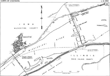
Lock and Dam No. 16
Date of Construction: 1933-1937
Location: Near Muscatine, Iowa
General Setting: Lock and Dam No. 16 is located about 1 mile upstream from Muscatine, and 457.2 miles above the confluence of the Ohio and Mississippi Rivers. The complex stretches across the river at a point where the valley is wide. The earthen embankment section of the dam straddles portions of Hog Island in the main channel.
Dam: The movable dam has 12 non-submersible Tainter gates, each 20 feet high and 40 feet long; 3 submersible Tainter gates of the same dimensions; and 4 non-submersible roller gates, 20 feet high and 80 feet long. The dam system also includes a linear, concrete capped, ogee spillway; and a submersible earth and sand-filled dike.
Lock: Lock dimensions are the standard 110 by 600 feet, with additional footings for an auxiliary lock of standard dimensions. Lock lift is 9 feet. Normal upper pool elevation is 545.0; about 14 feet above the tail waters below the dam at low water. When both pools are at their normal elevation, the difference is reduced to 9 feet or less.
History/Significance: Dam No. 16 was the last dam in the Rock Island District to employ non-submersible roller gates, as well as Tainter gates, submersible and non-submersible, which had steel sheeting on only one side. It was also, however, the first dam in the district in which all the Tainter gates were operated by line shafts and motors housed in installations above each gate, rather than from locomotive hoist cars running on the dam's service bridge. The lock and dam elements were completed at a cost of $5,688,000.
General Contractors:
Lock and Dam: Central Engineering Company, Davenport, Iowa [27]
|
| Site Plan, Lock and Dam No. 16. (U.S. Army Corps of Engineers, Rock Island District) (click on image for a PDF version) |

|
| Lock and Dam No. 16. (Peter A. Rathbun) |
Lock and Dam No. 17
Date of Construction: 1935-1939
Location: Near New Boston, Illinois
General Setting: Lock and Dam No. 17 is 437.1 miles above the confluence of the Ohio and Mississippi Rivers. The complex stretches across a wide portion of river where there are several marshy islands. The Upper Mississippi River Wildlife and Fish Refuge occupies the islands, marshes, and sloughs on the Iowa shore both upstream and downstream from the dam.
Dam: The movable dam has 8 submersible Tainter gates, 20 feet high and 64 feet long; and 3 submersible roller gates, 20 feet high and 100 feet long. The dam system also includes one non-overflow earth and sand-filled dike; two transitional dikes; and a submersible earth and sand-filled dike.
Lock: Standard dimensions of 110 by 600 feet, with footings for an auxiliary lock. Lock lift is 8 feet. Normal upper pool elevation is 536.0, about 12 feet above the tail waters of the dam at low water. When both pools are at their normal elevation, the difference is reduced to 8 feet or less.
History/Significance: The site of Lock and Dam No. 17 was inaccessible from the nearest highway. As a result, the contractors for the lock had to construct a 3.7 mile long entrance road. The remoteness of the site caused other problems. Not enough workers could commute to the job site from their homes. As a result, the Massman Construction Company and the Massman-Peterman Company built a workers' camp near the lock and dam site. This camp consisted of eleven 16-man bunk houses and a large mess hall. During the peak of construction in July 1936, 626 men were employed on the project. The lock and dam elements were built at a cost of $5,638,000.
General Contractors:
Lock: Massman Construction Company and Massman-Peterman Company, Kansas City, Missouri
Dam: Maxon Construction, Dayton, Ohio [28]

|
| Site Plan, Lock and Dam No. 17. (click on image for a PDF version) |

|
| Lock and Dam No. 17. (Peter A. Rathbun) |
Lock and Dam No. 18
Date of Construction: 1934-1937
Location: Seven miles above Burlington, Iowa
General Setting: The complex is 410.5 miles above the confluence of the Mississippi and Ohio Rivers. The bottom lands on both shores are flat and punctuated by sloughs, marshes, and reefs. The river is dotted with low islands of various sizes. The Oquawka State Wildlife Refuge is adjacent to the lock and dam complex on the Illinois shore. The installation's esplanade interrupts a levee and functions as part of the Henderson River diversion that converted Turkey Island into an extension of the Illinois shore.
Dam: The dam system is composed of 14 submersible Tainter gates, 20 feet high and 60 feet long; and 3 submersible roller gates, 20 feet high and 100 feet long. All of the gates submerge to a depth of 8 feet. The dam system also includes a submersible earth and sand-filled dike; a non-overflow earth and sand-filled dike; and two transition dikes.
Lock: Lock dimensions are the standard 110 by 600 feet, with additional footings for an auxiliary lock of standard dimensions. Lock lift is 10.5 feet. Normal upper pool elevation is 528.0, about 13 feet above the tail waters of the dam at low water. When both pools are at their normal depth, the difference is reduced to 9.8 feet or less.
History/Significance: Dams Nos. 11 and 18 were the first in the Rock Island District to employ submersible, elliptical Tainter gates. They were also the first two dams in the district to utilize submersible roller gates. This complex also involved the diversion of Henderson River so that it entered the Upper Mississippi immediately below the lock and dam complex. The lock and dam were built at a cost of $5,886,000. During the peak of construction in September 1934, the project employed 960 men as laborers, and 74 men as supervisors. Average employment was 478 laborers and 44 supervisors.
General Contractors:
Lock: Maxon Construction Company. Dayton, Ohio
Dam: S.A. Healy Company, Chicago, Illinois [29]

|
| Site Plan, Lock and Dam No. 18. (click on image for a PDF version) |

|
| Tainter Gates, Dam No. 18. (Peter A. Rathbun) |
Lock and Dam No. 19
Date of Construction: (1910-1914) 1952-1957
Location: Keokuk, Iowa
General Setting: The complex is 364.2 miles above the confluence of the Ohio and Mississippi Rivers.
Dam: Privately built and owned, the dam was built in 1913 and includes 119, rectangular, sliding gates.
Lock: Constructed between 1952-1957, the main lock is 110 by 1,200 feet, twice the size of the standard 9-foot channel lock. Normal upper pool elevation is 518.2 feet; about 38.2 feet above the tail waters of the dam at low water. The Keokuk and Hamilton Water Power Company Lock, built between 1910 and 1914, is closed off by a permanent, steel pile, cell structure.
History/Significance: Lock and Dam Complex No. 19 was not built as part of the original 9-Foot Channel Project. The Des Moines Canal Bullnose was built between 1867-70 as part of the Corps' 4-foot channel project. The Keokuk and Hamilton Water Power Company built the dam, power plant, dry dock, and original lock between 1910-14. Between 1952-57, the Corps built the 1,200-foot lock, control houses, utility building, and esplanade in four stages. Stage I, 1952-54, encompassed the construction of the lock's lower approach. During Stage II, 1954-56, the lock was constructed. Stage III, completed in 1954, involved the manufacture and delivery of electrical control equipment and the upstream gate operating equipment. Stage IV, 1956-1957, included the installation of the power, control, and lighting system. The 1950s elements of the complex cost approximately $13,500,000. During the peak of construction, 415 people were employed. Elements of Lock and Dam No. 19 were listed on the National Register of Historic Places in October 1978.
General Contractors:
Stage I: McCarthy Improvement Company, Davenport, Iowa
Stage II: Jones Construction Company, Charlotte, North Carolina
Stage III: Oil Gear Company, Milwaukee, Wisconsin
Stage IV: Evans Electrical Construction Company, Omaha, Nebraska [30]

|
| Lock and Dam No. 19. (click on image for a PDF version) |
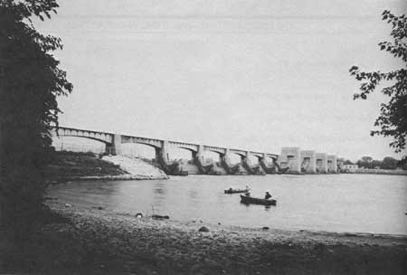
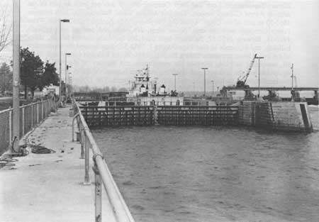
Lock and Dam No. 20
Date of Construction: 1932-1935
Location: Between Canton, Missouri, and Meyer, Illinois
General Setting: Lock and Dam No. 20 is 343.2 miles above the confluence of the Ohio and Mississippi Rivers. The complex stretches across the river at a point where the valley is quite wide, about 5 miles wide at the level of the lock and dam. A levee and the Gregory Diversion Ditch separate the complex from the town of Canton.
Dam: The movable dam has 3 non-submersible roller gates, 20 feet high and 60 feet long; 34 non-submersible Tainter gates, 20 feet high and 40 feet long; and 6 submersible Tainter gates, 20 feet high and 40 feet long. The submersible Tainter gates submerge 3 feet.
Lock: Lock dimensions are 110 by 600 feet, with additional footings for an auxiliary lock of standard dimensions. Lock lift is 10.5 feet. Normal upper pool elevation is 480.0; this is about 15 feet above the tail waters of the dam at low water. When both pools are at their normal depths, the difference is reduced to 10 feet or less.
History/Significance: Dam No. 20 was the first dam in the Rock Island District to include Tainter gates. The plans originally called for all of the Tainter gates to be operated by hoist cars traveling on the dam's service bridge. However, the district modified two Tainter gates so that they were individually operated by line shafts and motors housed in installations above each gate. This operating machinery worked so well that all subsequent Tainter gates in the 9-Foot Channel Project, regardless of which district they were in, utilized line shafts and motors. The lock and dam elements of complex No. 20 cost $4,450,000. In 1986, Lock and Dam No. 20 became the first complex in the Rock Island District to undergo major rehabilitation.
General Contractors:
Lock: Maxon Construction Company, Dayton, Ohio
Dam: S.A. Healy Company, Detroit, Michigan, and Davenport, Iowa [31]

|
| Lock and Dam No. 20. (Peter A. Rathbun) |
|
| Lock No. 20, Downstream View. (Peter A. Rathbun) |
Lock and Dam No. 21
Date of Construction: 1933-1939
Location: Quincy, Illinois
General Setting: Lock and Dam No. 21 is located 324.9 miles above the confluence of the Ohio and Mississippi Rivers. The complex stretches across the river at a point where the valley is wide with flat bottom land on either side of the river. The city of Quincy lies on the low bluffs along the river just upstream from the complex.
Dam: The movable dam has 10 submersible, elliptical Tainter gates, 20 feet high and 64 feet long; and 3 submersible roller gates, 20 feet high and 100 feet long. The dam system also includes two earth and sand-filled transitional dikes, and a submersible earth dike.
Lock: Lock dimension are the standard 110 by 600 feet, with additional footings for an auxiliary lock of standard dimensions. Lock lift is 10.5 feet. Normal upper pool elevation is 470.0; approximately 16 feet above the tail waters of the dam at low water. When both pools are at their normal depths, the difference in elevation is reduced to 11 feet or less.
History/Significance: Lock and Dam No. 21 was a group "D" priority. However, because it was located adjacent to Quincy, Illinois—which had an acute unemployment problem—the installation was built before some of the other, higher priority installations in the Rock Island District. The lock, central control station, and esplanade were completed by August 1935. At that point, however, there was no money available with which to begin the dam. As a result, representatives from Quincy began to vigorously—and successfully—lobby for Federal money to construct the dam as a work relief project. The lock and dam elements were completed at a cost of $5,721,000.
General Contractors:
Lock: Joseph Meltzer Inc., New York, New York
Dam: McCarthy Improvement Company, Davenport, Iowa [32]

|
| Site Plan, Lock and Dam No. 21. (click on image for a PDF version) |
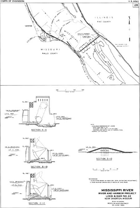
Lock and Dam No. 22
Date of Construction: 1934-1939
Location: Saverton, Missouri
General Setting: Lock and Dam No. 22 is located 301.2 miles above the confluence of the Ohio and Mississippi Rivers. Bluffs rise over 200 feet above the river west of the lock; east of complex the valley is quite wide.
Dam: The movable dam has 9 non-submersible Tainter gates, 25 feet high and 60 feet long; 1 submersible Tainter gate, 25 feet high and 60 feet long; and 3 submersible roller gates, 25 feet high and 100 feet long. Completing the dam system are two transition dikes, and a submersible earth and sand-filled dike.
Lock: Lock dimensions are the standard 110 by 600 feet, with additional footings for an auxiliary lock of standard dimensions. Lock lift is 10.5 feet. Normal upper pool elevation is 459.5, about 16.5 feet above the tail waters of the dam at low water. When both pools are at their normal depths, the difference in elevation is reduced to 10.5 feet or less.
History/Significance: It was on the submersible roller gates at Dam No. 22 that the Rock Island District introduced Poiree dam trestles to mitigate scour problems. The trestles were subsequently used as a retrofit solution on other project dams. It was also on this dam's submersible roller gates that the St. Paul District Hydraulic Laboratory conducted the tests that led to the design of stilling basins for roller gates. The Rock Island District also incorporated an experimental design for a submersible roller gate with end shields at Dam No. 22. Additionally, the Rock Island District introduced a new type of non-submersible, truss-type Tainter gate in Dam No. 22. The lock and dam elements were built at a cost of $5,135,000. During the peak of construction, 959 people were employed on the installation.
General Contractors:
Lock: Joseph Meltzer, Inc., New York, New York
Dam: Massman Construction Company, Kansas City, Missouri [33]
|
| Site Plan, Lock and Dam No. 22. (click on image for a PDF version) |
| <<< Previous | <<< Contents>>> | Next >>> |
rmr/2/chap10b.htm
Last Updated: 01-Feb-2008