|
Gateways to Commerce: The U.S. Army Corps of Engineers' 9-Foot Channel Project on the Upper Mississippi River |

|
CHAPTER X
The Locks and Dams—and Those Who Built Them (continued)
The St. Paul District
The St. Paul District was originally in charge of constructing that portion of the 9-foot channel on the Upper Mississippi River between St. Paul to the mouth of the Wisconsin River near Prairie du Chien, Wisconsin. The district began constructing the project in 1930. By 1940, Corps workers had substantially completed eight lock and dam complexes—Nos. 3, 4, 5, 5A, 6, 7, 8 and 9—with the exception of some ancillary service elements such as lockmasters' dwellings, garages, and access roads. In 1939, the St. Paul District's duties were expanded when it took over the administration of Lock and Dam No. 10 at Guttenberg, Iowa, which had previously been under the supervision of the Rock Island District. [2]
The St. Paul District also includes four lock and dam installations that were not constructed as part of the original 9-Foot Channel Project. The authorizing act for the 9-foot channel called for the incorporation of two existing lock and dam complexes into the system. The Twin Cities Lock and Dam (1894-1932), located between Minneapolis and St. Paul, became Lock and Dam No. 1. The Hastings Lock and Dam, constructed by the Corps between 1928 and 1930, became Lock and Dam No. 2. In 1937, Congress also authorized a 4.6 mile extension of the 9-foot channel at its upstream end, and the Corps constructed 2 additional complexes: the Upper St. Anthony Falls Lock and Dam, and the Lower St. Anthony Falls Lock and Dam. The Corps built these structures, respectively, in 1963 and 1956. [3]
In 1923, Major Charles F. Williams headed the St. Paul District office, which then consisted of the barest minimum of personnel. Charles Wade was Chief Administrator. Five years later, Western Division Engineer General Thomas Jackson spearheaded an overall restructuring of the Corps' activities, including those in the St. Paul District. As a result, administrative and engineering functions were separated, and chains of command were established in the engineering division. Following the restructuring, Colonel Wildurr Willing replaced Major Williams as head of the St. Paul District. Colonel Willing, who was assisted by Military Assistant for Special Assignments 1st Lieutenant Heath Twitchell, headed the St. Paul District until 1933, at which time he was replaced by Major Dwight F. Johns. Major Johns supervised the 9-Foot Channel Project until 1937, when Captain Frank Albrecht served briefly as Acting District Head. In July 1937, Lieutenant Colonel Phillip B. Fleming replaced Albrecht. Colonel John Moreland became head of the St. Paul District in October 1939, overseeing the remainder of work done under the 9-foot channel program as of 1940. [4]
Surveyman M.L. Betzel oversaw the hired labor. Engineering responsibilities were divided into three sections. Howard M. Anderly headed Section No. One, and supervised improvements on the Upper Mississippi from St. Paul to the mouth of the Wisconsin River, as well as various improvements on the St. Croix River. Anderly also oversaw the reconstruction of Locks and Dams Nos. 1 and 2. Section No. One included an engineer, W.D. Fairchild; two assistant engineers, V.C. Funk and James R. Johnson; and a junior engineer, Elmer J. Christenson, who was assigned to Fairchild. A construction supervisor, William P. Schmoker, and a gasoline engineman, William G. Straub, also worked in Section No. One. Schmoker supervised the work of most of the surveyors, the rock quarry overseer, the dredger engineers, and other workmen. [5]
|
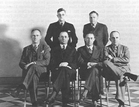
| The District Engineer and Staff of the St. Paul District, c. 1936. Front row, left to right: Captain Fisher S. Blinn, Major Dwight F. Johns (District Engineer), Captain Frank Albrecht, and Captain Keith R. Barney. Second row: Edward E. Ezell and Howard M. Anderly. (American Heritage Center, University of Wyoming) |
Herbert Vassant headed Section No. Two. The duties of this section included Hastings Lock and Dam flowage rights, St. Croix River permits, special investigations, and Federal Power Commission reports. Hibbert M. Hill oversaw Section No. Three, and handled flood control surveys; 9-foot channel surveys (particularly the location of dam sites and survey work); supervision of hydraulic testing at the University of Iowa; studies for the Mississippi River Survey Board; engineering and operations of reservoirs at the Mississippi headwaters; model studies; office studies; and stream measurement.
Hibbert Hill had important impacts on the 9-Foot Channel Project in the St. Paul District. A graduate of the University of Minnesota, Hill served with the Coast and Geodetic Survey before joining the Corps in 1927. Hill also taught hydraulic engineering at the University of Minnesota, where he had access to information and talented personnel. Assistant Engineer James R. Johnson, Junior Engineer Elmer Christenson, Assistant Engineer Edward F. Brownell, Assistant Engineer Henry J. Manger, Assistant Engineer Leo M. Buhr, and Assistant Engineer George O. Guesmer all received training at the University of Minnesota.
Martin E. Nelson, the district's assistant engineer in charge of hydraulic model studies conducted at the University of Iowa, was also a graduate of the University of Minnesota. Nelson had also studied at the Royal Technological Institute in Stockholm, Sweden. Since the designs of the roller gates used in the 9-foot channel had been used in Sweden, it is reasonable to assume that Nelson's expertise was a welcome asset in the St. Paul District. The unique roller/Tainter gate combination systems of the 9-Foot Channel Project were among the first known applications of their kind in the United States. Working models for these designs were handled, in part, by Nelson. Nelson's working models answered important questions concerning foundation stability, ice discharge, accurate pool levels, navigation currents, and related matters. [6]
The work carried on at the University of Iowa testing laboratories, as well as the research of civilian engineers such as Hibbert Hill and Martin Nelson, contributed significantly to the overall project in matters of gate technology and general dam design. Jerome Ackerman, Associate Engineer with the St. Paul District, provided much of the expertise on soil mechanics. Ackerman, who was later with the Corps' Missouri River Division, was influenced by the work of Arthur Casagrande, head of the Soil Mechanics Laboratory at Harvard University. Testing in areas such as foundation stability by technicians such as Elmer Christenson and W.W. Ralphe and their work on Lock and Dam No. 3 resulted in the use of new materials, techniques, and innovative applications, providing the basis for future progressive engineering designs. These innovations and others like them resulted in such later developments as the 80-foot Tainter gates located at Clarksville, Missouri, in the Rock Island District, and the 125-foot roller gates on the Ohio River at Gallipolis—among the largest installations of their kind ever built in the United States. [7]
Locks and Dams Nos. 1 and 2
The 1930 authorizing act for the 9-Foot Channel Project called for the incorporation of 2 existing lock and dam complexes into the system: Locks and Dams Nos. 1 and 2.
Lock and Dam No. 1
Twin Cities (Ford) Lock and Dam
Located between Minneapolis and St. Paul, Minnesota, the Corps of Engineers began constructing this installation in 1894 as part of the 5-foot channel concept. The complex was later modified during the 1907 6-foot channel project, and includes a reinforced concrete overflow dam, and 2 navigation locks that measure 56 by 400 feet. A hydroelectric plant located at the dam's east end provides power to a nearby Ford automobile factory.
Lock and Dam No. 2
Hastings Lock and Dam
Located at Hastings, Minnesota, this lock and dam complex was constructed by the Corps of Engineers between 1928 and 1930. Built at a time when the Corps was still committed to open water navigation on the Upper Mississippi, the installation includes a 100-foot wide navigable pass adjacent to the lock. The dam was also built with 20 Tainter gates, and acted as an "engineering link" between the 6-foot channel and the 9-foot channel system.
Note: Gate dimensions are approximate figures based on the general notations found in U.S. Army Corps of Engineers' publications. For example, roller gates are often shown as a standard 80 by 20 feet. However, in the more detailed construction history notations, gate sizes are often given exactly as 88 feet, 10 1/2-inches long and 15 feet in diameter. Similar approximations apply to Tainter gates. In both instances, the dimensions should be taken only as approximations for use in categorizing gate sizes and styles, and not as exact measurements.
|
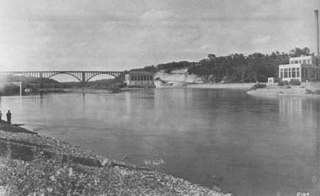
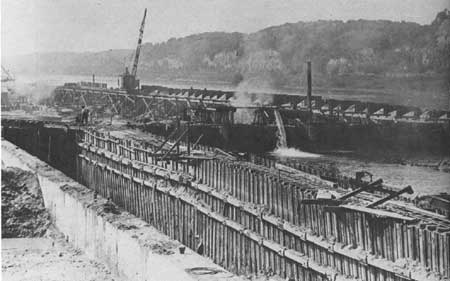
| (Top) Lock and Dam No. 1 with Ford Bridge in the background, ca. 1929. (Photo credit: Gibson) (Minnesota Historical Society) (Bottom) Construction of Lock and Dam No. 2, ca. 1929. (Photo credit: St. Paul Daily News) (Minnesota Historical Society) |
Lock and Dam No. 3
Date of Construction: 1935-1940
Location: Six miles upstream from Red Wing, Minnesota
General Setting: The complex is on the Minnesota side of the river. The old river channel at this point normally measured about 600 feet; floodwaters increased the width to 2-1/2 miles at times.
Dam: The movable dam is 365 feet long, and consists of 4 submersible roller gates, 20 feet high and 80 feet long. The gates submerge to a depth of 5 feet. Each gate has its own independent hoist machinery. The gates and operating machinery were constructed and delivered to the site by the Lakeside Bridge and Steel Company of Milwaukee, Wisconsin. The dam foundations are set in sand.
Lock: Standard 110 by 600 feet, with additional gate and footings for an auxiliary lock. Upper normal pool elevation is 675 feet; lower pool elevation is 667 feet. Depth on upper miter sill is 17 feet; lower miter sill is 14 feet. Lock lift is 8 feet. The lock foundations are set in sand, silt, and clay.
History/Significance: Specific items of engineering significance include the exclusive use of submersible roller gates in the movable dam; the use of "Z" sheet piling in the abutment walls; and the replacement of all dam substrata. Prior to the construction of the dam, the Corps replaced approximately 200,000 cubic yards of unstable substrata with 130,000 cubic yards of river sand in order to provide a more stable foundation for the dam structure. The lock and dam elements of the complex were completed at a cost of $3,730,000. Fifty-three injuries took place during construction; no fatalities occurred.
General Contractors:
Lock: Spencer, White & Prentis, Inc., New York, New York
Dam: A. Gutherie Co., St. Paul, Minnesota
Hallett Construction Co., Crosby, Minnesota [8]
|
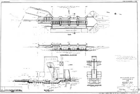
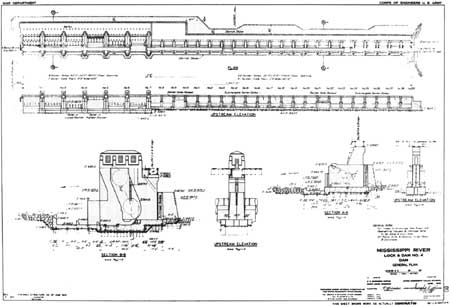
| (Top) Similar to all the construction drawings for the 9-Foot Channel Project dams, the plan for Dam No. 3 shows the arrangement of dam gates, as well as sectional views of the gates and piers. Dam No. 3 General Plan, September 1936. (U.S. Army Corps of Engineers, St. Paul District) (click on image for a PDF version) (Bottom) Roller Gates, Dam No. 3. (Clayton B. Fraser, Fraserdesign) |
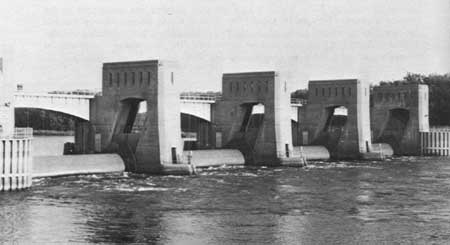
Lock and Dam No. 4
Date of Construction: 1932-1938
Location: Alma, Wisconsin
General Setting: Lock and Dam No. 4 is located about 90 miles below Minneapolis. The river bank was about 800 feet wide at the time of construction; high water increased this width by approximately 2,000 feet.
Dam: The movable dam consists of 6 submersible roller gates and 22 Tainter gates. Each roller gate is 20 feet high and 60 feet long, and is submersible for 3 feet. The roller gates—designed and built by the Treadwell Construction Co. of Midland, Pennsylvania, and installed by the McClintic-Marshall Corp. of Chicago—are all equipped with individual operating machinery. The Tainter gates, constructed and installed by the McClintic-Marshall Corp., are 15 feet high and 35 feet long. Tainter gates nos. 16, 17, 27, and 28 submerge 3 feet; the rest of the Tainter gates are non-submersible. The Tainter gates are controlled by a gasoline hoist that moves to each gate by means of a rail system on top of the bridge. The dam foundation consists of piles in sand and gravel.
Lock: Lock dimensions are the standard 110 by 600 feet. Lock lift is 7 feet. Upper normal pool elevation is 667 feet. Depth on upper miter sill is 17 feet; lower miter sill is 13 feet. The foundation is piles in sand and gravel.
History/Significance: At the time it was built, this dam's combination of roller and Tainter gates was believed to have been the first of its type to be constructed. Cold weather created several problems during construction of the complex. Approximately 120 timber pilings split and had to be pulled and replaced; engineers speculated that sap freezing in the green pilings may have caused the splitting. Ten major injuries, 296 minor injuries, and 3 deaths were reported during the construction of the dam.
General Contractors:
Lock: Ouillmette Construction and Engineering Co., Chicago, Illinois
Dam: United Construction Co., Winona, Minnesota [9]
|
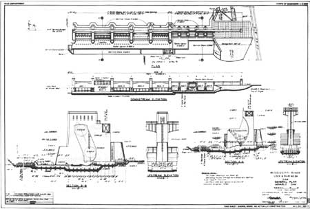
| General Plan for Dam No. 4, June 1933. (U.S. Army Corps of Engineers, St. Paul District) (click on image for a PDF version) |
Lock and Dam No. 5
Date of Construction: 1933-1939
Location: Near Minneiska, Minnesota; 5.5 miles upstream of Fountain City, Wisconsin
General Setting: Lock and Dam No. 5 is 114.75 miles downstream from Minneapolis. The river was, at the time of construction, about 2 to 2-1/2 miles wide with the main channel at the foot of the bluff. The river normally maintained a width of 800 feet, widening to 2 miles in flood stages.
Dam: The 1,619-foot-long movable dam is composed of 24 non-submersible Tainter gates, 15 feet high and 35 feet long; 4 submersible Tainter gates of the same dimensions; and 6 submersible roller gates, 20 feet high and 60 feet long. Both the submersible Tainter gates and the roller gates submerge to a depth of 3 feet. All of the gates are located between concrete piers topped with a steel service deck. The dam foundation is set on piles in sand.
Lock: Standard 110 by 600 feet, with the upper gate of an auxiliary lock located in the main channel next to the Minnesota shoreline. Lock lift is 9 feet. Upper normal pool elevation is 660 feet. Depth on upper miter sill is 18 feet; lower miter sill is 12 feet. The foundation consists of piles in sand and gravel.
History/Significance: Lock and Dam No. 5 was a group "A" priority, and the second installation completed in the St. Paul District. Typical of other 9-foot channel installations, the roller gates on Dam No. 5 were located in the main channel, where they could handle the greatest flooding and heavy ice flow conditions. One fatal accident, involving a private craft, occurred during the construction of the dam. In 1934, the site hosted a presidential visit by Franklin Roosevelt.
General Contractors:
Lock: Edward E. Gillen Co., Milwaukee, Wisconsin
Dam: Merritt-Chapman & Whitney Corp., Cleveland, Ohio [10]
|
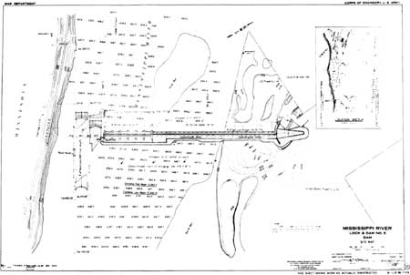
| Site Map for Dam No. 5, August 1933. (U.S. Army Corps of Engineers, St. Paul District) (click on image for a PDF version) |
Lock and Dam No. 5A
Date of Construction: 1934-1938
Location: Three miles above Winona, Minnesota
General Setting: At the time of construction, the site consisted of low, swampy ground separated by three sloughs: Blackbird Slough, Straight Slough, and Crooked Slough. Many small lakes were in the area, interrupted by sections of relatively high ground. The lock and dam site, located in the middle of the river channel, incorporated a number of islands into its earth dike system. The location of the complex in a slough on the left side of Islands 67 and 68 allowed for the main channel to serve an exclusive spillway function.
Dam: The movable dam is 682 feet long and consists of 5 submersible roller gates, 20 feet high and 80 feet long; and 5 non-submersible Tainter gates, 15 feet high and 35 feet long. The roller gates submerge 3 feet. A 1,000-foot overflow spillway, 5,344-foot earth dike, and connecting stub dike were also completed as part of the dam system.
Lock: Standard 110 by 600 feet dimensions, with standard auxiliary lock elements. Lock lift is 5.5 feet. Upper normal pool elevation is 651 feet. Depth on upper miter sill is 18 feet; lower miter sill is 12.5 feet. Foundation consists of piles in sand.
History/Significance: The original plan for the 9-foot channel system did not include this installation. However, due to pooling problems projected as a result of the construction of Lock and Dam No. 6 in conjunction with the City of Winona, this installation was designed and given a "B" priority.
General Contractors:
Lock: McCarthy Improvement Co., Davenport, Iowa
Dam: United Construction Co., Winona, Minnesota [11]
|
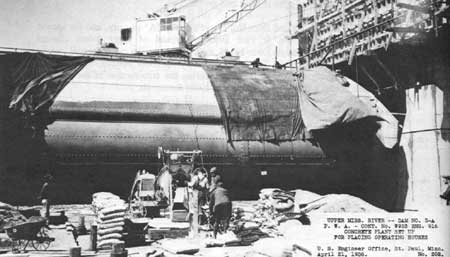
| (Top) General Plan for Lock and Dam No. 5A, October 1934. (U.S. Army Corps of Engineers, St. Paul District) (click on image for a PDF version) (Bottom) Workers setting up concrete plant at Dam No. 5A, April 1936. (U.S. Army Corps of Engineers, St. Paul District) |
Lock and Dam No. 6
Date of Construction: 1933-1938
Location: Trempealeau, Wisconsin
General Setting: The complex is 139 miles below Minneapolis. The normal river stage was 1/4-mile wide, with a high water width of approximately 2,000 feet. Steep sandstone bluffs bordered the mile-wide valley. The area was a popular summer home location.
Dam: The movable dam is 893 feet long and consists of 5 submersible roller gates, 20 feet high and 80 feet long; and 10 non-submersible Tainter gates, 15 feet high and 35 feet long. The roller gates submerge 3 feet, and were constructed and erected by the American Bridge Co. of Gary, Indiana—in conjunction with the S. Morgan Smith Co. of York, Pennsylvania; Cutler-Hammer, Inc.; Century Electric; and Foot Brothers. The Tainter gates were constructed and erected by the American Bridge Co. Dam foundations are piles in sand and clay.
Lock: Standard 110 by 600 feet dimensions, with standard auxiliary lock elements. Upper normal pool elevation is 645.5 feet. Depth of upper miter sill is 17 feet; lower miter sill is 12.5 feet. Lock lift is 6.5 feet. The lock foundation consists of piles in sand and gravel.
History/Significance: The Tainter gates in Dam No. 6 were the first in the St. Paul District to employ independent operating machinery instead of hoist car systems. During construction, the frozen river was sometimes used as a work base, as the ice was often 12 to 18 inches thick. Piles were dragged over the ice by teams of draft animals. The construction of Lock and Dam No. 6 also resulted in innovations in pile driving. Timber pilings—elm, maple, hickory, ash, oak, yellow birch, and pine—were driven by new, skid-type, pile drivers built on the job site by a contractor. A new method of keeping the pile drivers level was also developed by the contractor.
General Contractors:
Lock and Dam: Spencer, White & Prentis, Inc., New York, New York [12]
|
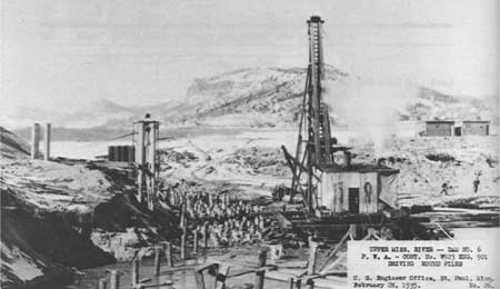
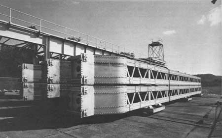
| (Top) Driving Piles at Dam No. 6, February 1935. (U.S. Army Corps of Engineers, St. Paul District) (Bottom) Roller Gate Bulkheads, Dam No. 6. The individual gate bays on the dam can be closed off with bulkheads and then drained for repairs. (Clayton B. Fraser, Fraserdesign) |
Lock and Dam No. 7
Date of Construction: 1933-1940
Location: Dresbach, Minnesota; near Onalaska, Wisconsin
General Setting: The site is 4.5 miles above LaCrosse, Wisconsin, and approximately 150.7 miles below Minneapolis. Normal river width was approximately 1,000 feet; the terrain consisted of bottom lands interrupted by sections of high land. French Island, located 8,000 feet east of the eastern bank, separates the Black River from the rest of the Mississippi Valley.
Dam: The 940-foot movable dam has 5 submersible roller gates, 20 feet high and 80 feet long; and 9 non-submersible and 2 submersible Tainter gates, 20 feet high and 35 feet long. The submersible Tainter gates submerge 2 feet; the roller gates submerge 3 feet. The gates were fabricated by the Bethlehem Steel Co. The dam system also includes a fixed, 670-foot submersible dam, and a 9,003-foot earth dike. Foundations are piles in sand.
Lock: Standard 110 by 600 foot dimensions, with an auxiliary lock 110 by 360 feet. Lock lift is 8 feet. Upper normal pool elevation is 639 feet. Depth on upper miter sill is 18 feet; lower miter sill is 12 feet. The foundation consists of piles in sand and gravel.
History/Significance: Originally scheduled to be nearer LaCrosse, this complex was relocated because of water level problems connected with the LaCrosse site. The design of the complex was heavily influenced by French Island, which was incorporated into the design as a natural dike, and the Dresbach Slough, which was reopened to provide the upper approach to the lock. The complex was built at a cost of $6,776,000.
General Contractors:
Lock: Nolan Brothers, Minneapolis, Minnesota;
Minneapolis Dredging Co., Minneapolis;
Dearborn Electrical Construction Co., Chicago, Illinois
Dam: Warner Construction Co., Chicago, Illinois [13]
|
| (Top) Roller Gate, Dam No. 7. (Clayton B. Fraser, Fraserdesign) (Bottom) Like many of the 9-foot channel installations, the Lock and Dam No. 7 site includes a fixed submersible dam and earth dike. (Clayton B. Fraser, Fraserdesign) |
Lock and Dam No. 8
Date of Construction: 1933-1938
Location: Genoa, Wisconsin
General Setting: The complex is 173.4 miles below Minneapolis. At the time of construction, the river at this location was approximately 1,200 feet wide at normal stages, increasing to 13,000 feet at periods of high water. The terrain consisted of sand flats with brush and willows; timber was located on the higher ground.
Dam: The movable dam is 934.5 feet long and consists of 5 submersible roller gates, 20 feet high and 80 feet long; and 8 non-submersible and 2 submersible Tainter gates, each 15 feet high and 35 feet long. The roller gates submerge to a depth of 3 feet; the submersible Tainter gates to a depth of 2 feet. Two submersible dams with lengths of 937.5 and 1,337.5 feet and an earth-filled dike with a total length of 15,720 feet are also included in the complex. The foundation consists of piles in sand and gravel.
Lock: Lock dimensions are the standard 110 by 600 feet, with a planned auxiliary lock 110 by 360 feet. Lock lift is 11 feet. Upper normal pool elevation is 631 feet. Depth on upper miter sill is 22 feet; lower miter sill is 14 feet. The foundation materials consist of piles in sand, gravel, and broken clay.
History/Significance: The design of Lock and Dam No. 8 was not dictated by unusual river hydrology so much as for the need for a lock and dam system at that point of the river so that the 9-foot channel system might function properly. The complex was completed at an estimated cost of $7,728,000. Eighty-six accidents and one fatality occurred during dam construction; no accidents or fatalities were reported during construction of the lock.
General Contractors:
Lock: Jutton-Kelly Company, Milwaukee, Wisconsin
Dam: Siems-Helmers, Inc., St. Paul, Minnesota [14]
|
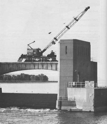
| Movable Crane on Dam No. 8 Bridge (Clayton B. Fraser, Fraserdesign) |
Lock and Dam No. 9
Date of Construction: 1936-1940
Location: Below Lynxville, Wisconsin
General Setting: Lock and Dam No. 9 is located 205.1 miles below Minneapolis. Prior to construction of the complex, the Mississippi River in this area was approximately 1,100 feet wide at normal levels, spreading to approximately 10,000 feet in flood stages.
Dam: The movable dam is 811 feet long, and consists of 5 submersible roller gates, 20 feet high and 80 feet long; and 2 submersible and 6 non-submersible Tainter gates, 15 feet high and 35 feet long. The roller gates submerge to a depth of 5 feet. The submersible Tainter gates, which submerge 2 feet, are located adjacent to the abutment pier. An earth dike extends from the far Tainter gate abutment northwest for 8,004 feet, and is intersected by a submersible dam 1,350 feet long. The foundation is made up of piles in sand.
Lock: Standard configuration of 110 by 600 feet, with a planned auxiliary lock of 110 by 360 feet. Lock lift is 9 feet. Upper normal pool elevation is 620 feet. Depth on upper miter sill is 16 feet; lower miter sill is 13 feet. The foundation is set on piles in sand.
History/Significance: Due to a good 6-foot channel and relatively trouble-free engineering and environmental characteristics, Lock and Dam No. 9 was a group "B" priority, and the second-to-last complex built by the St. Paul District. The complex was completed at an estimated cost of $8,287,000.
General Contractors:
Lock: Walter W. Magee Co., St. Paul, Minnesota
Dam: United Construction Co., Winona, Minnesota [15]
|
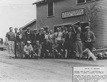
| Field Office Staff at Lock and Dam No. 9, c. 1936. (American Heritage Center, University of Wyoming) |
|
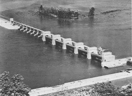
| Lock and Dam No. 9, May 1938. (U.S. Army Corps of Engineers, St. Paul District) |
Lock and Dam No. 10
Date of Construction: 1934-1937
Location: Guttenberg, Iowa
General Setting: Originally scheduled at Cassville, Wisconsin, the location of this complex was changed to Guttenberg because of flooding-related problems. The site is 16 miles below the mouth of the Wisconsin River, and 615.1 miles above Cairo, Illinois. At the time of construction, the river valley was approximately 2 miles wide and alluvial in nature, with a river bed level at about 590 feet above sea level. The town of Guttenberg is situated on a low ridge, the rest of the riverbank areas being overgrown with brush. The dam crosses Island 189.
Dam: The movable dam consists of 4 non-submersible roller gates, 20 feet high and 80 feet long; and 8 Tainter gates, 20 feet high and 40 feet long. Two Tainter gates are located at the west end of the dam, the other six are at the east end. Six of the Tainter gates are non-submersible. The Tainter gates on each end are submersible to a depth of 3 feet. All of the gates are equipped with independent operating machinery. The dam system also includes a 4,547-foot earth dike embankment, and a fixed ogee spillway that is 1,200 feet in length. The dam foundation is piles in sand.
Lock: Standard dimensions of 110 by 600 feet, with a planned auxiliary lock of 110 by 360 feet. Lock lift is 8 feet. Depth on upper miter sill is 15 feet; lower miter sill is 12 feet. The foundation is piles in sand.
History/Significance: Built under the supervision and direction of the Rock Island District, Lock and Dam No. 10 was transferred to the St. Paul District's jurisdiction on October 1, 1939. The complex was completed at an estimated cost of $6,647,000.
General Contractors:
Lock: Hanlon and Oakes, St. Paul, Minnesota
Dam: McCarthy Improvement Co., Davenport, Iowa [16]
|
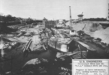
| Construction of Lock Wall, October 1934. (U.S. Army Corps of Engineers, St. Paul District) |
|
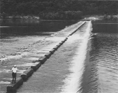
| Submersible Dike in Dam No. 10. (Clayton B. Fraser, Fraserdesign) |
| <<< Previous | <<< Contents>>> | Next >>> |
rmr/2/chap10a.htm
Last Updated: 01-Feb-2008