Area II
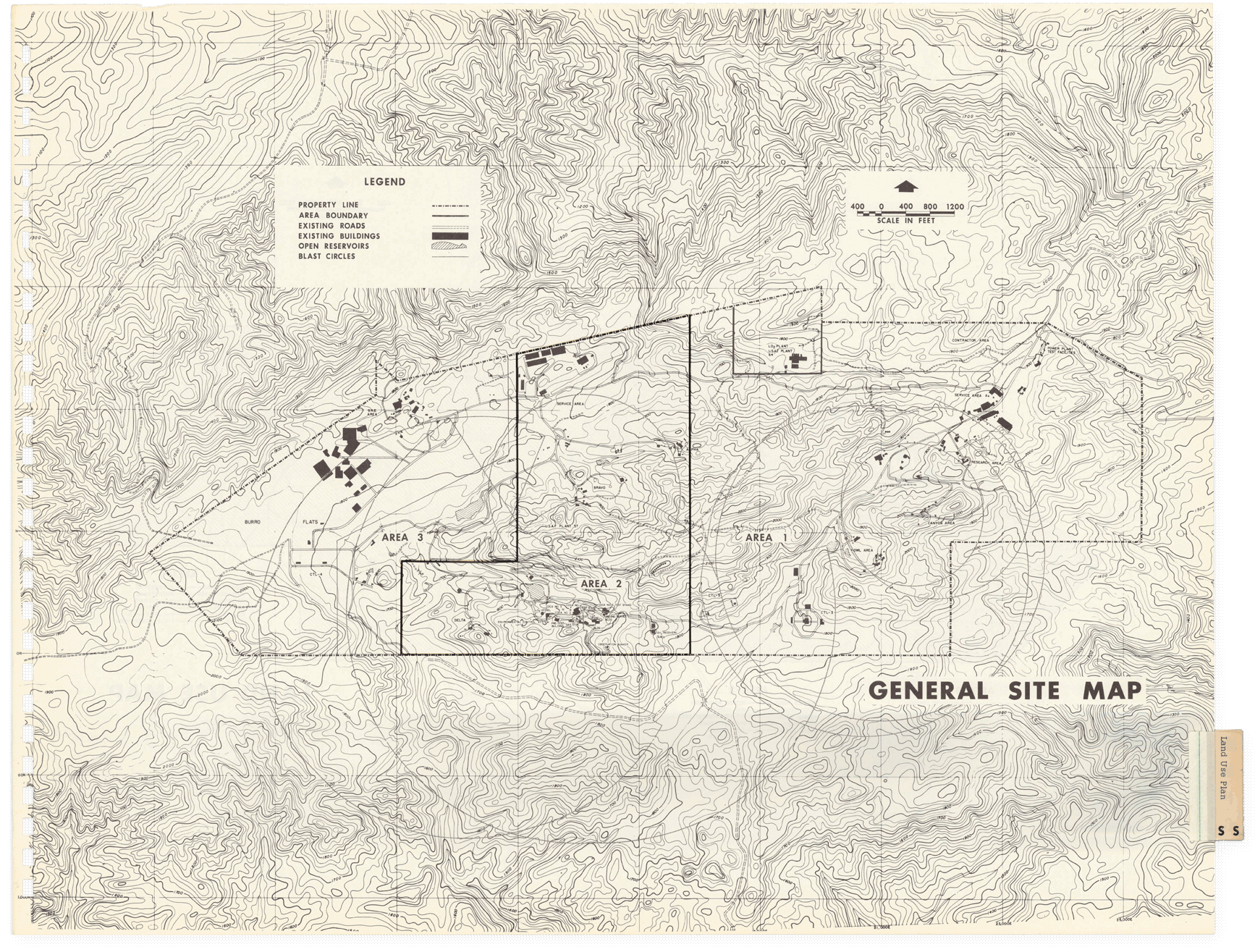
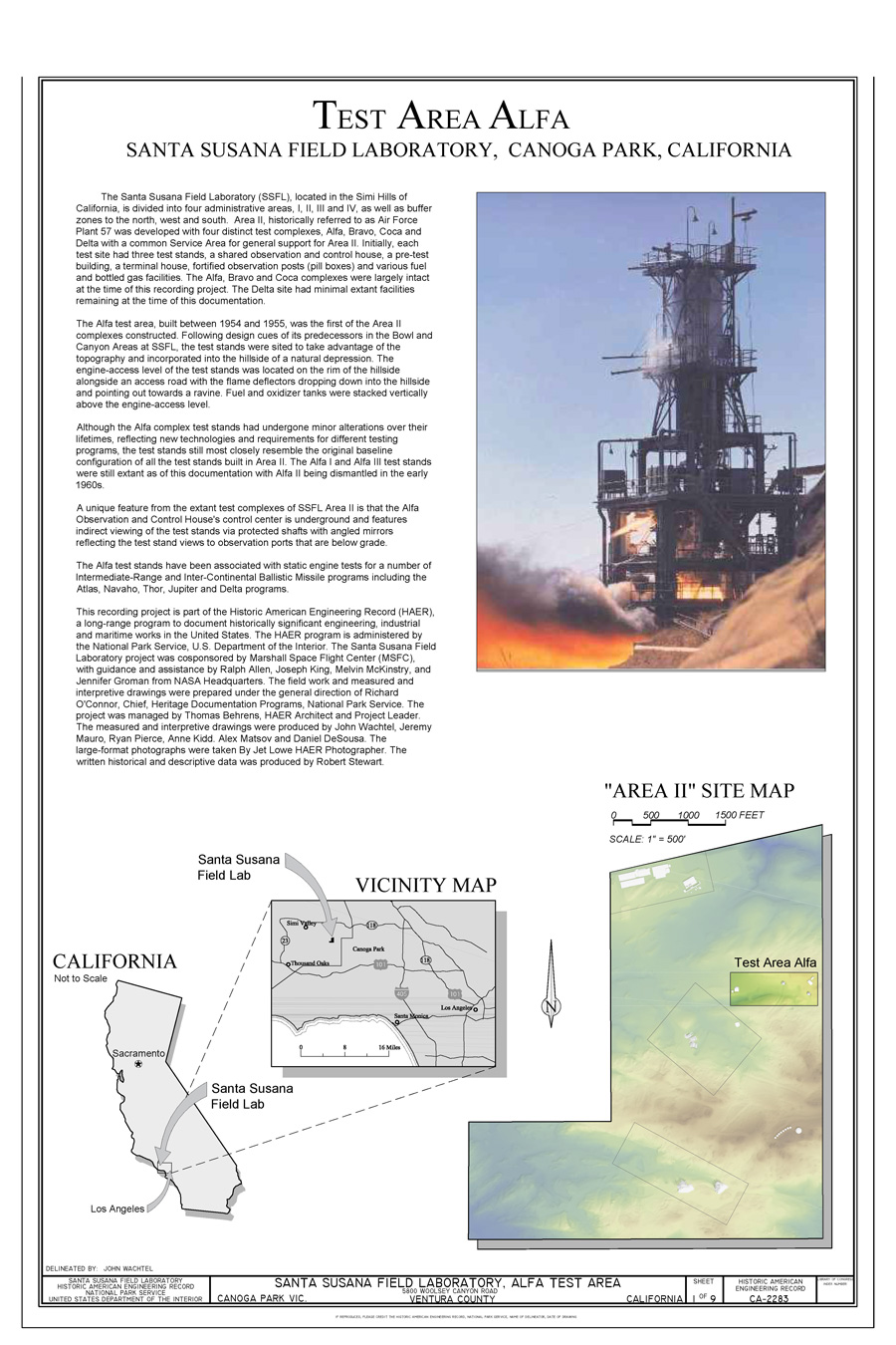
The Santa Susana Field Laboratory (SSFL) is located on approximately 2,850 acres in the Simi Hills in Ventura County, California. The Simi Hills are bordered on the east by the San Fernando Valley and to the north by Simi Valley. SSFL is divided into four administrative areas – Area I, Area II, Area III, and Area IV – and two "undeveloped areas." Areas I, III, and IV and the undeveloped areas are owned and operated by the Boeing Company. Area II, consisting of 409.5 acres, along with 41.7 acres in Area I, are owned by the U.S. Government and used by NASA. The U.S. Department of Energy (DOE) held a lease on land in Area IV.
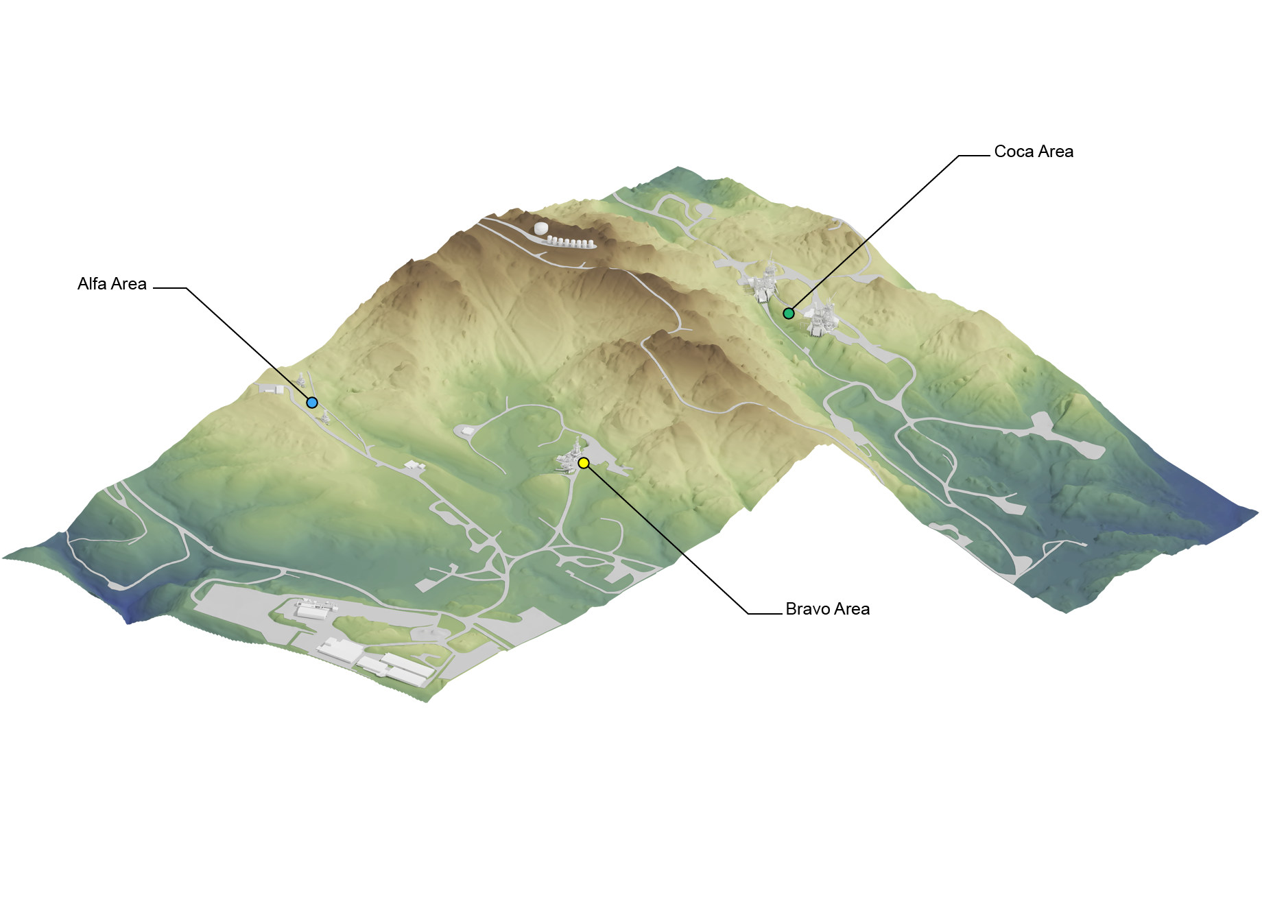
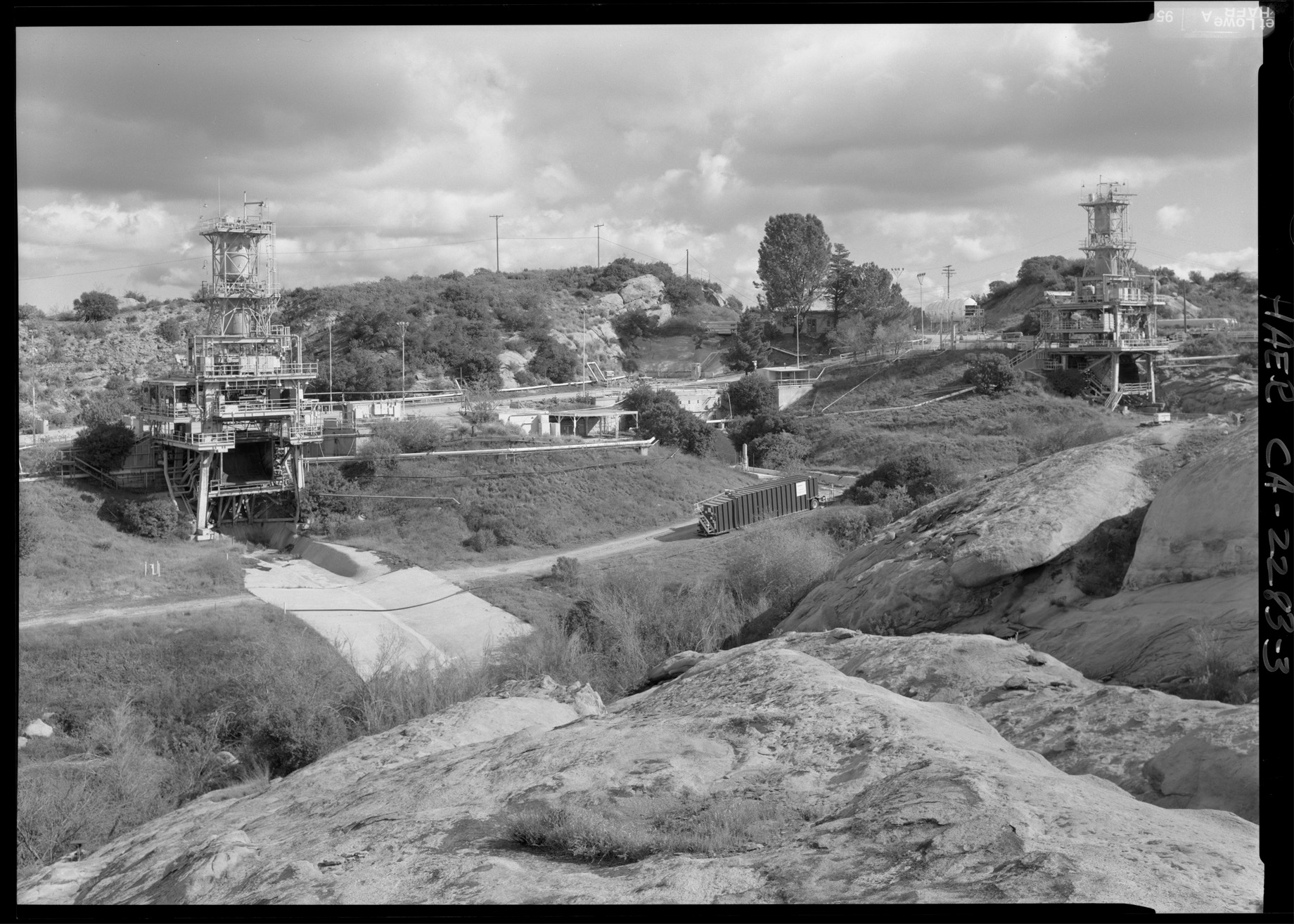
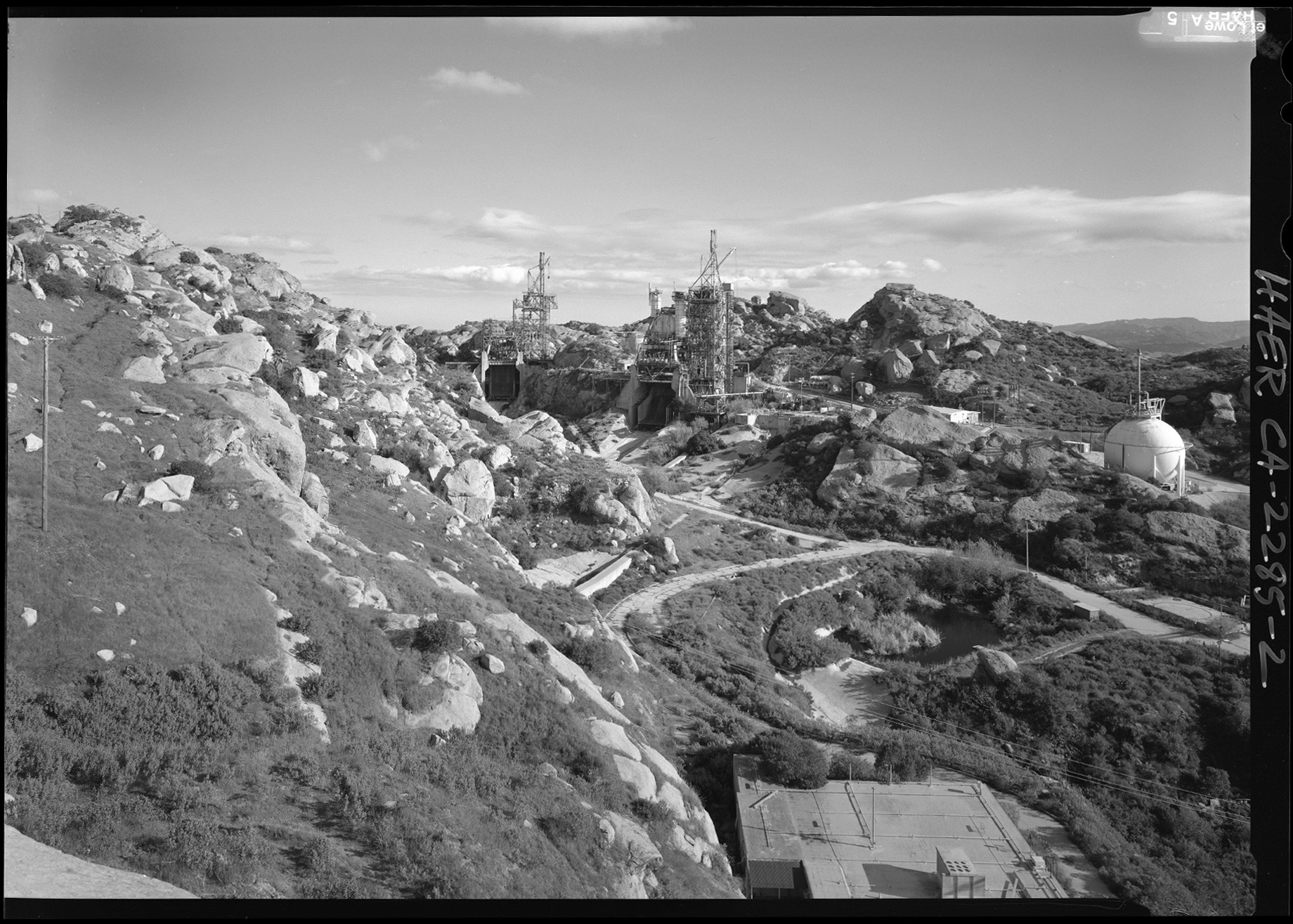
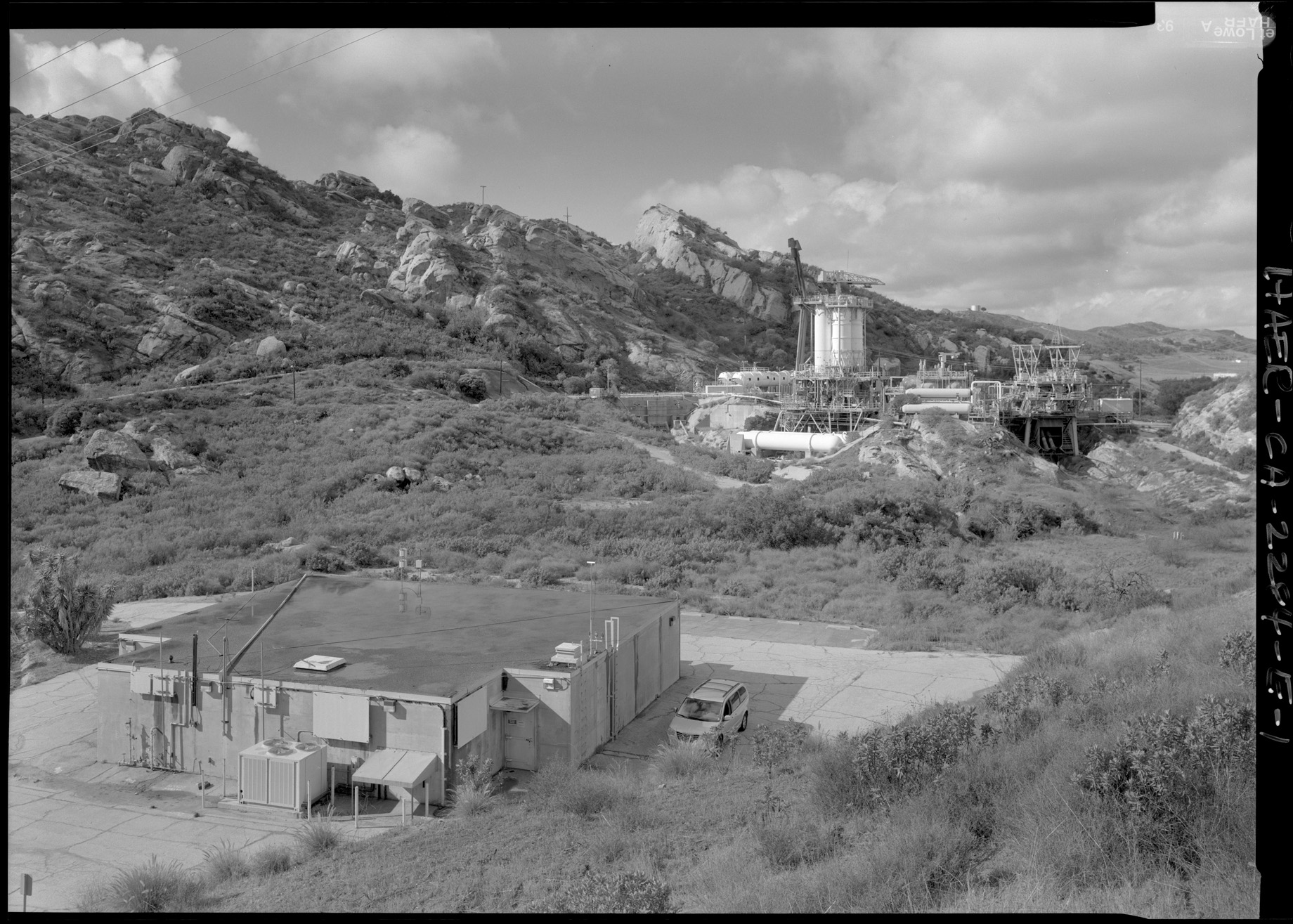
Initial design and construction of the various test areas within Area II took place from 1954 to 1958, although significant alterations would be made throughout the years. Test Areas Alfa, Bravo, and Coca possess characteristics unique from one another which demonstrate a variety of structures and methods for testing rocket engines and various components. All sites, however, were designed to take advantage of their surrounding landscapes. The rocky outcroppings of the Santa Susana Mountain Range provided a practical solution to a number of design considerations at the time, such as blast and sound suppression, and passive control of deluge water from the test stands.
Alfa Area
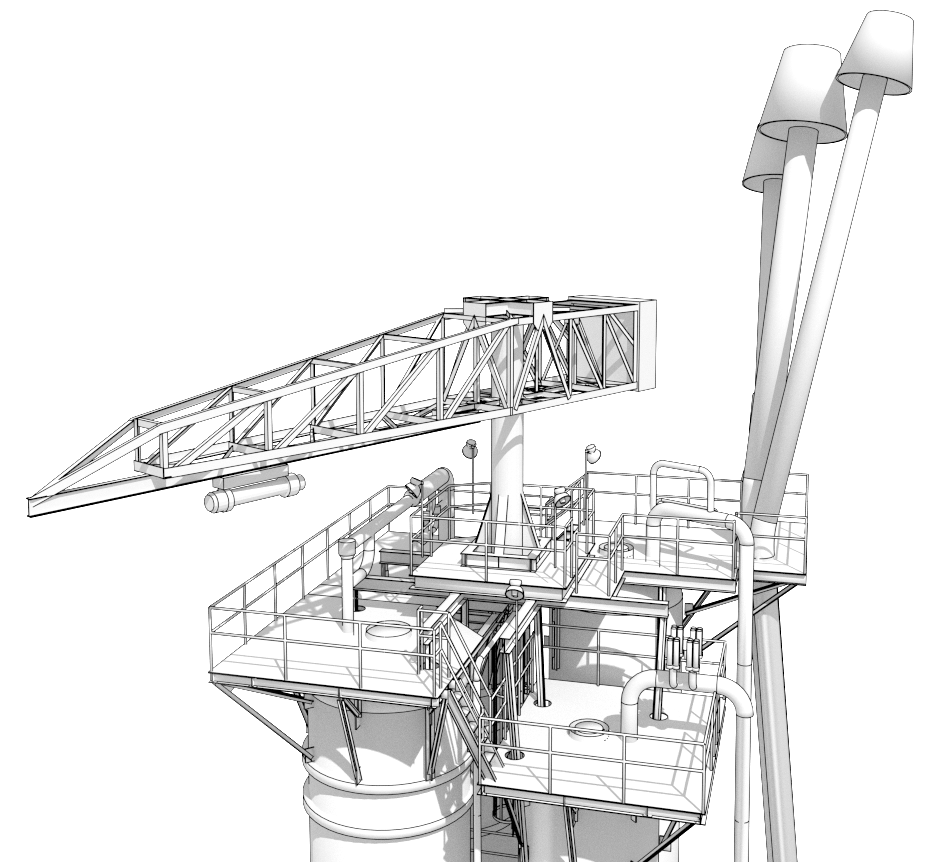
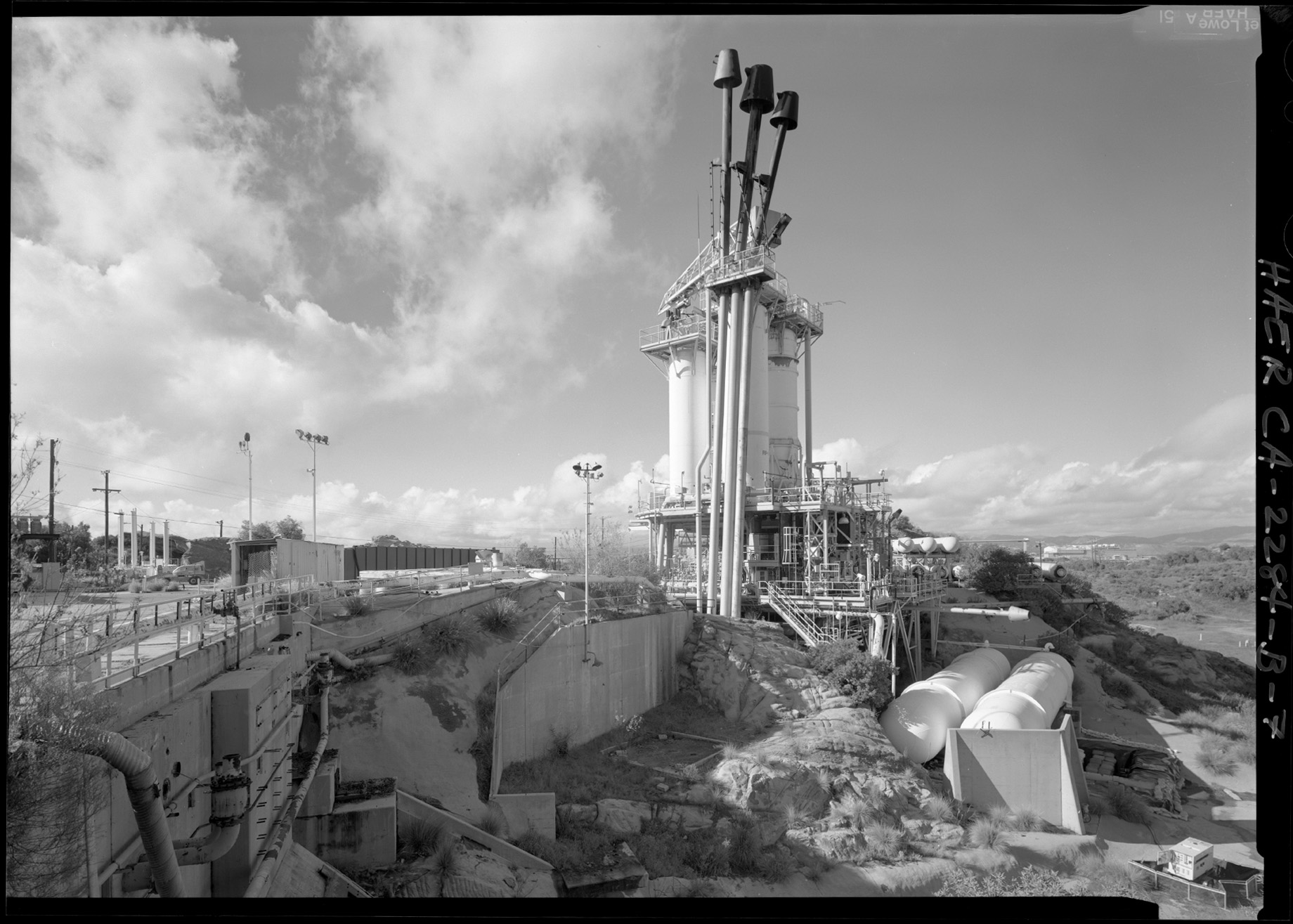
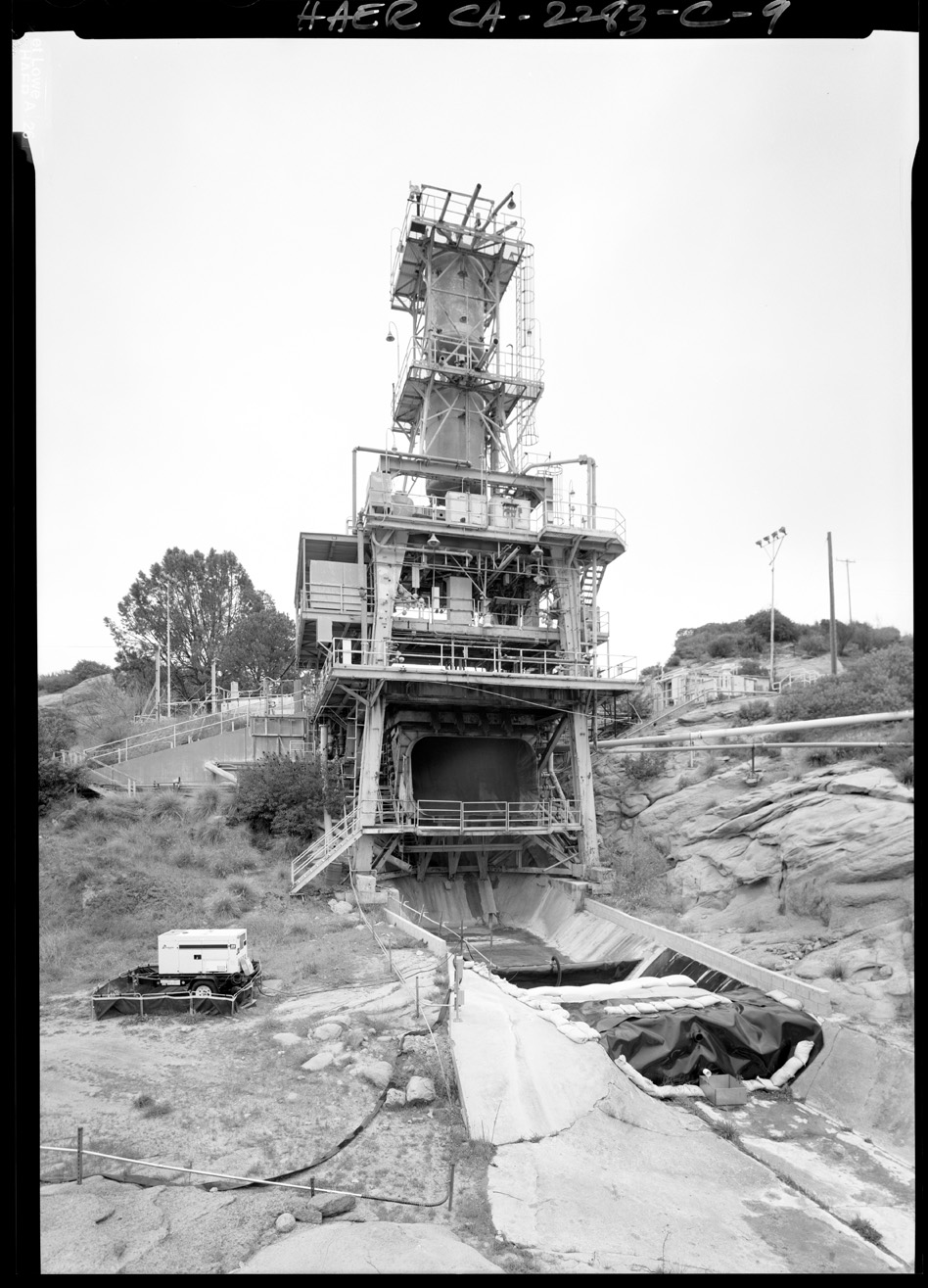
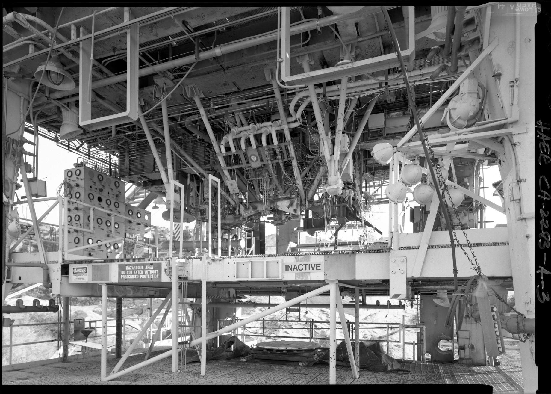
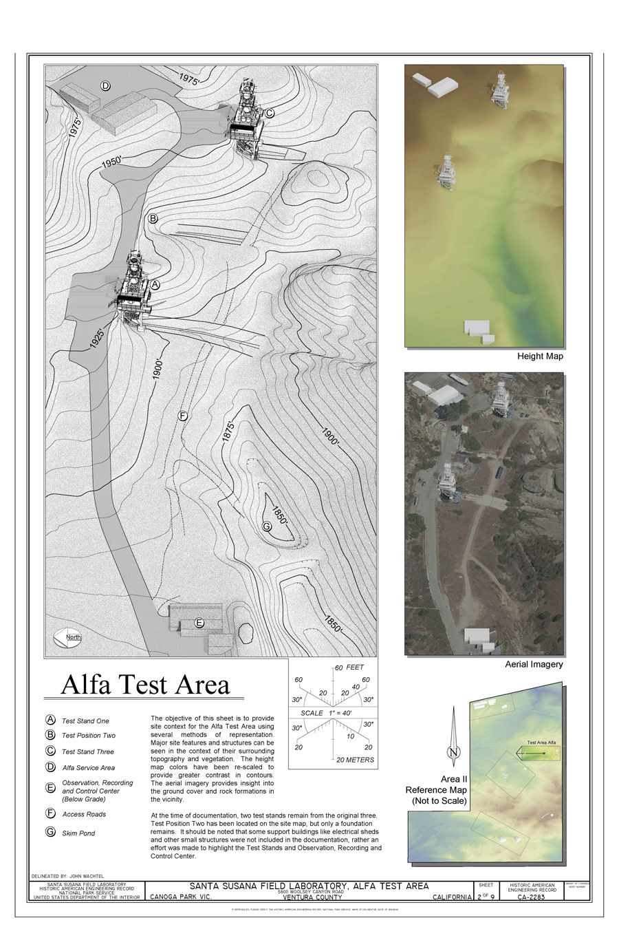
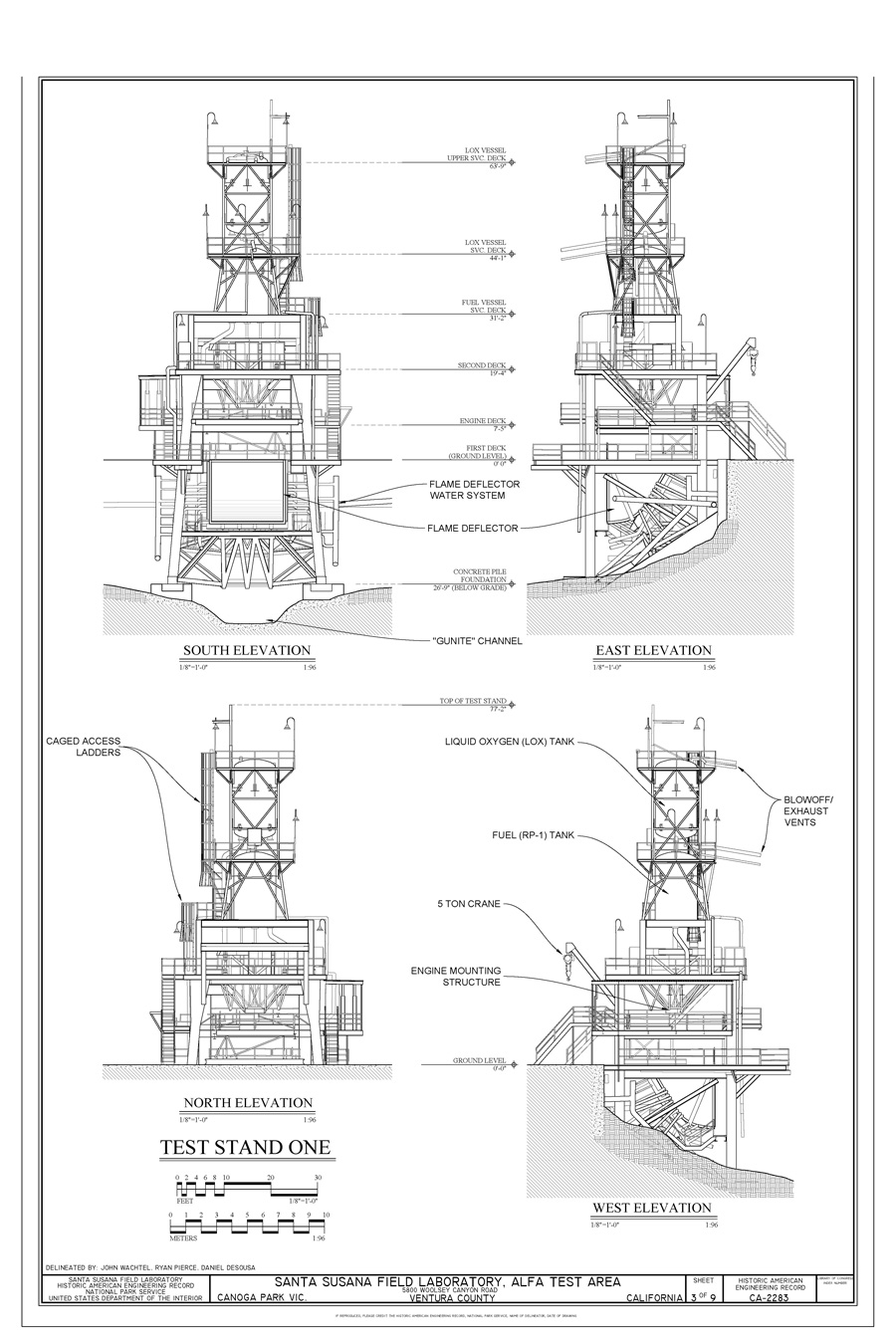
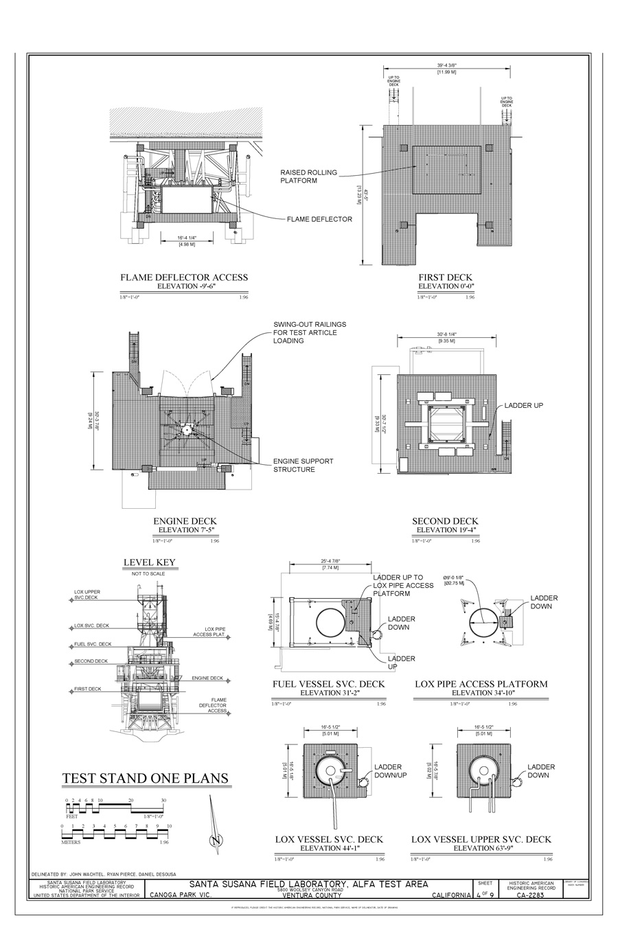
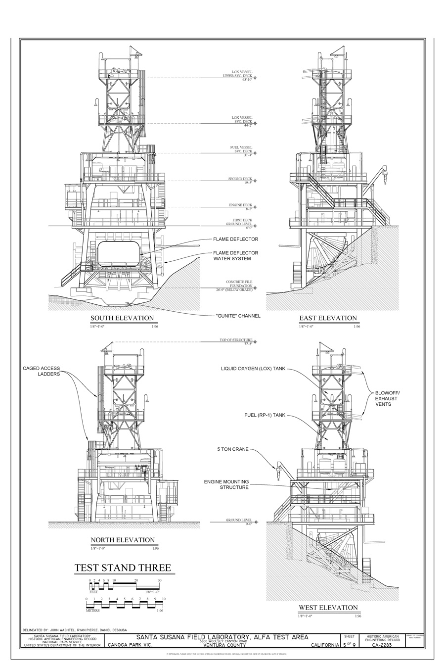
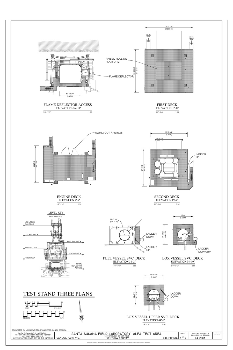
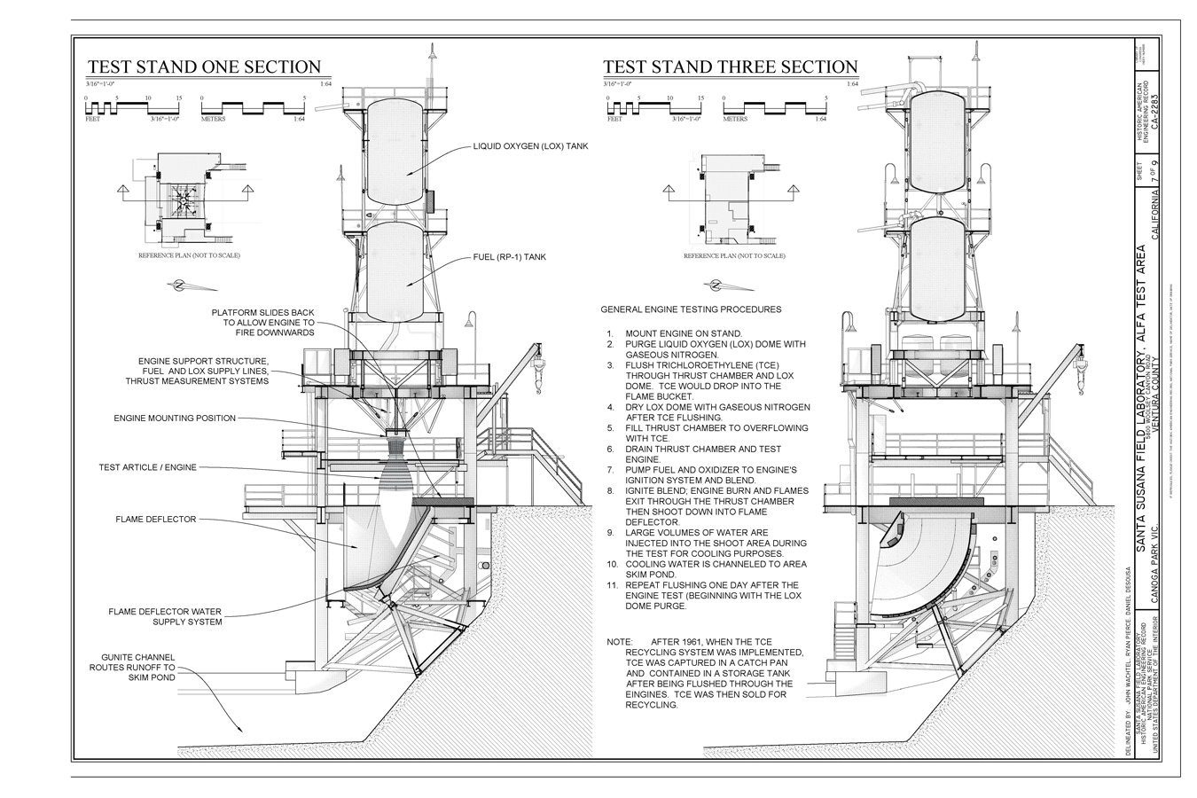
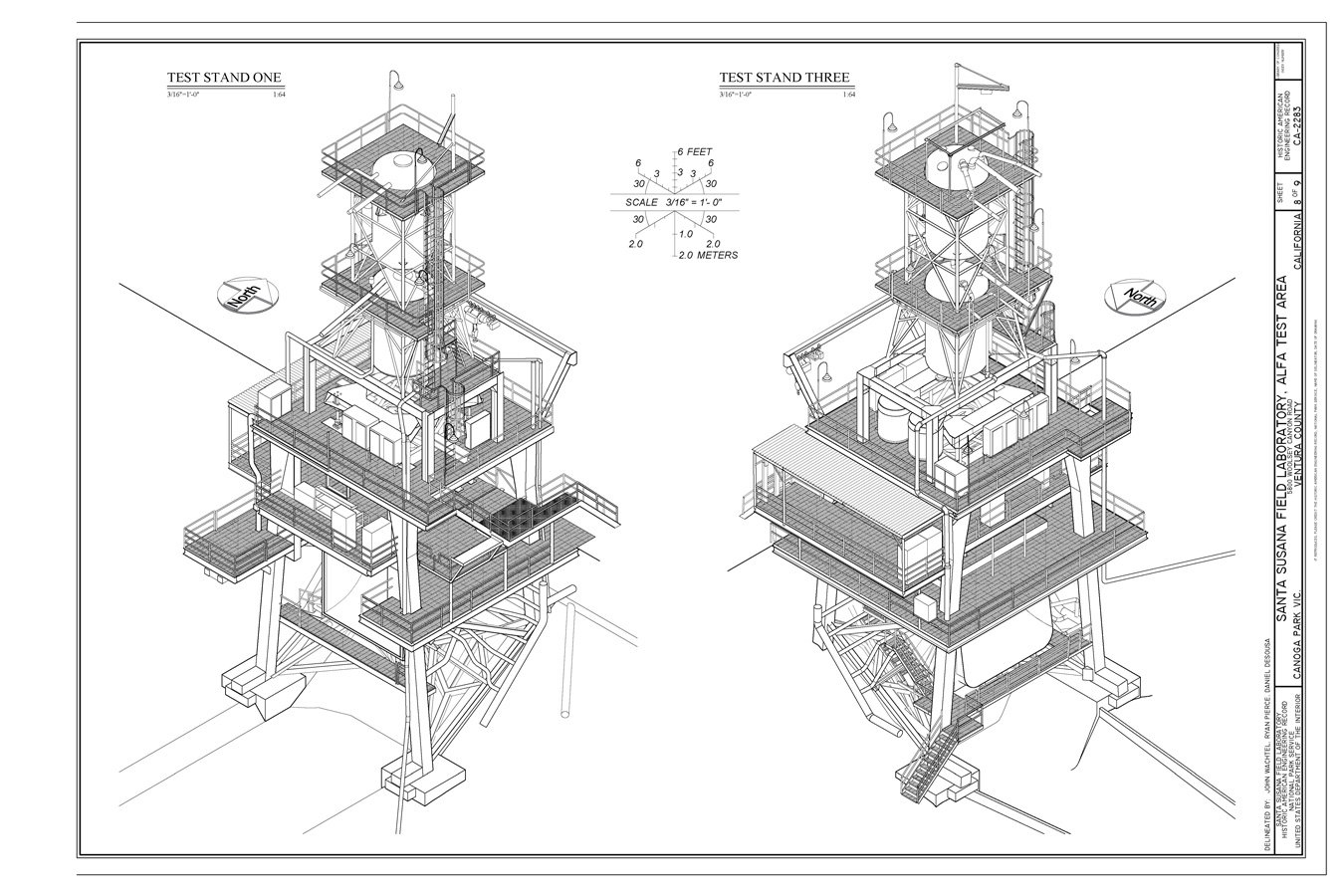
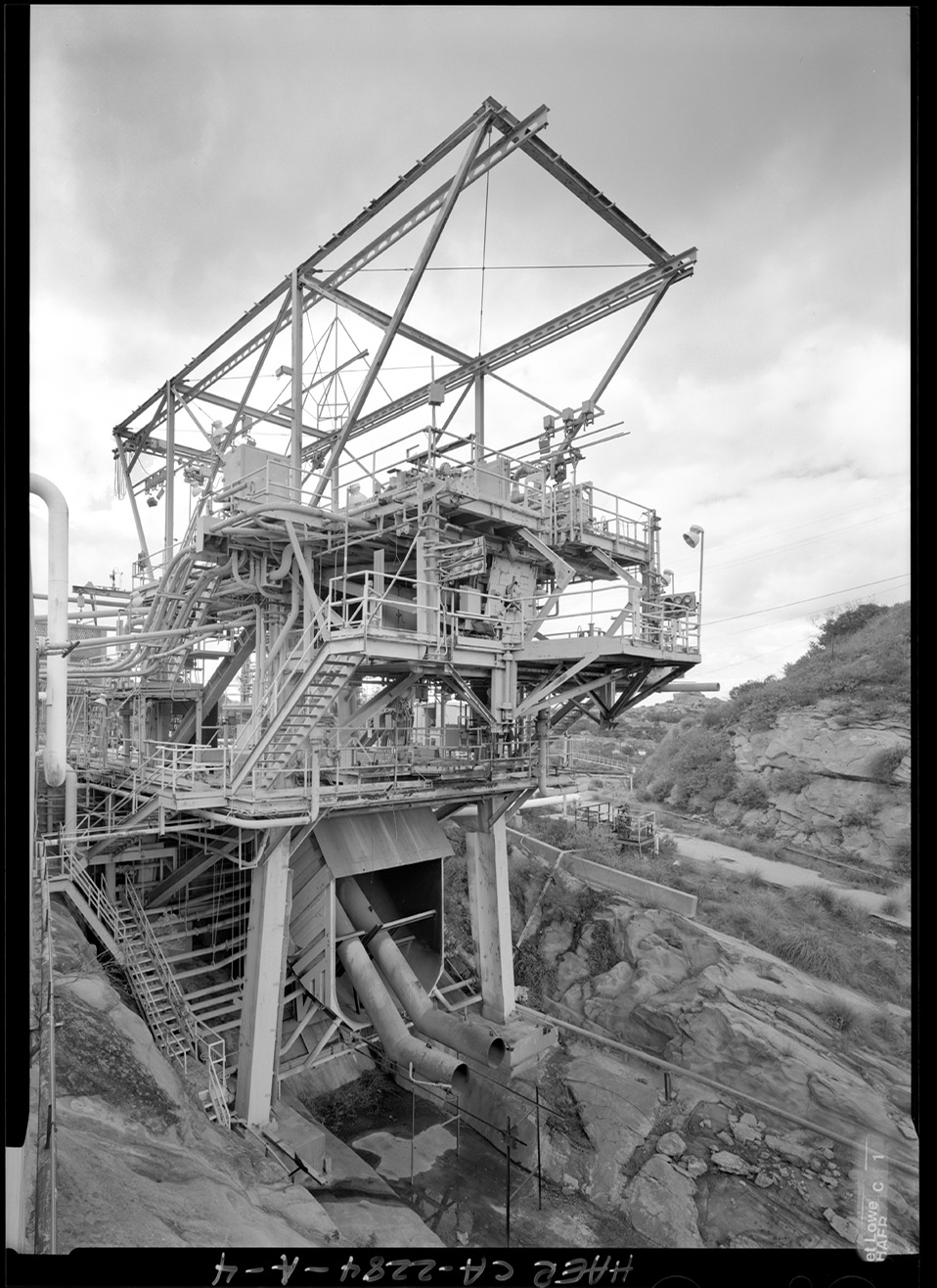
The Alfa test area, built between 1954 and 1955, was the first of the Area II complexes constructed. Following design cues of its predecessors in the Bowl and Canyon Areas at SSFL, the test stands were sited to take advantage of the topography and incorporated into the hillside of a natural depression. The engine-access level of the test stands was located on the rim of the hillside alongside an access road with the flame deflectors dropping down into the hillside and pointing out towards a ravine. Fuel and oxidizer tanks were stacked vertically above the engine-access level.
Although the Alfa complex test stands had undergone minor alterations over their lifetimes, reflecting new technologies and requirements for different testing programs, the test stands still most closely resemble the original baseline configuration of all the test stands built in Area II. The Alfa I and Alfa III test stands were still extant as of this documentation with Alfa II being dismantled in the early 1960s.
The Alfa test stands have been associated with static engine tests for a number of Intermediate-Range and Inter-Continental Ballistic Missile programs including the Atlas, Navaho, Thor, Jupiter and Delta programs.
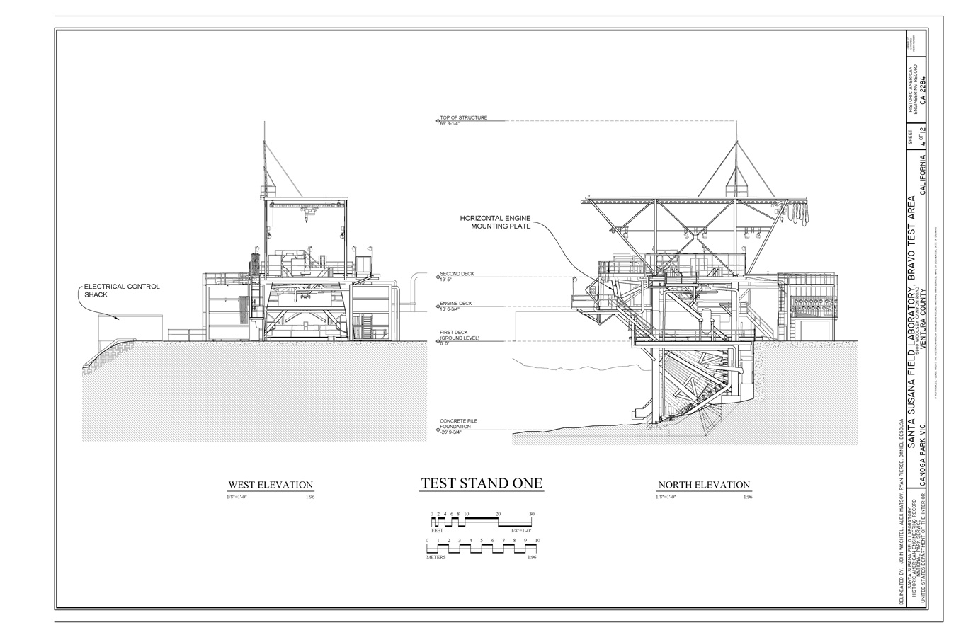
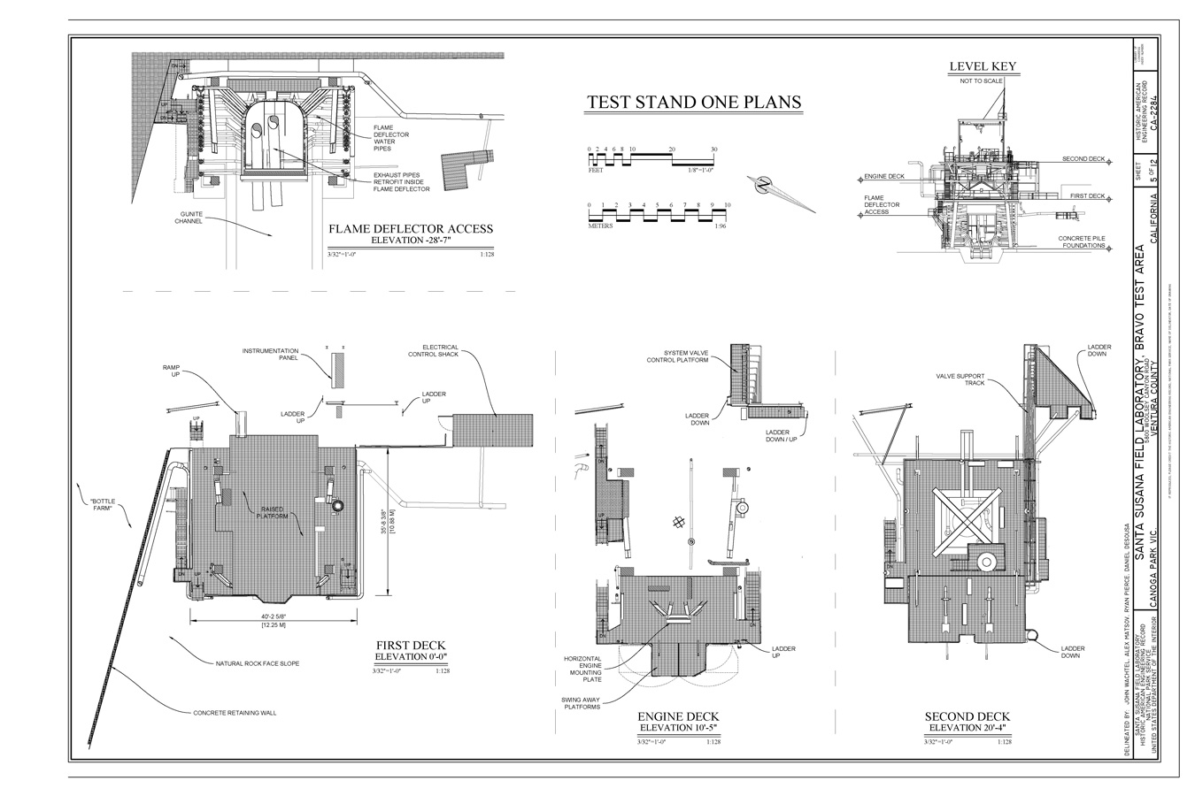
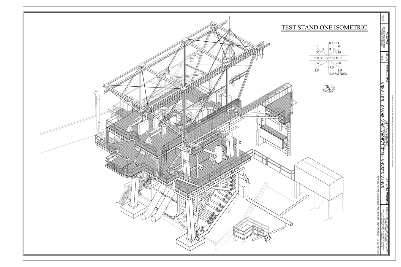
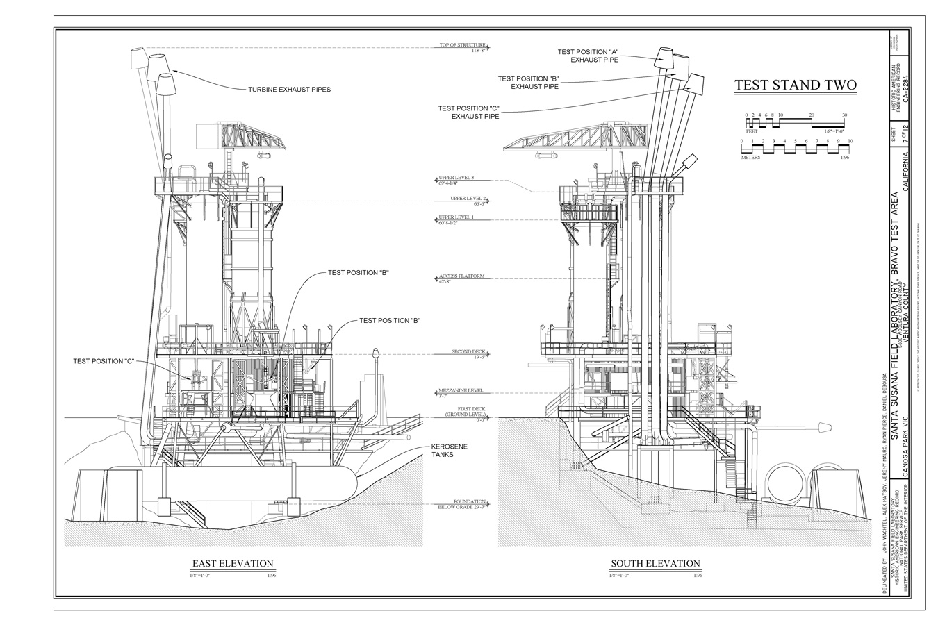
Bravo Area
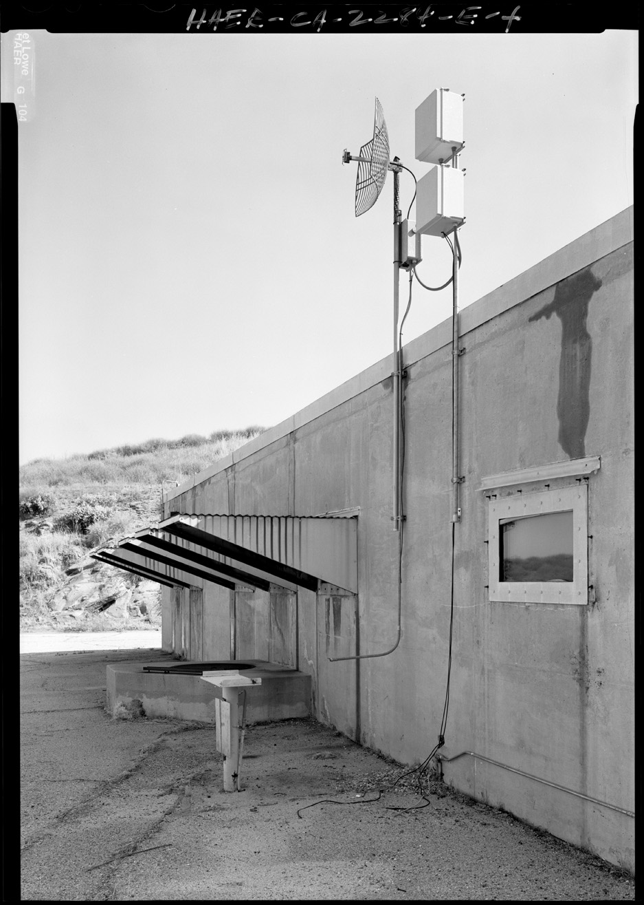
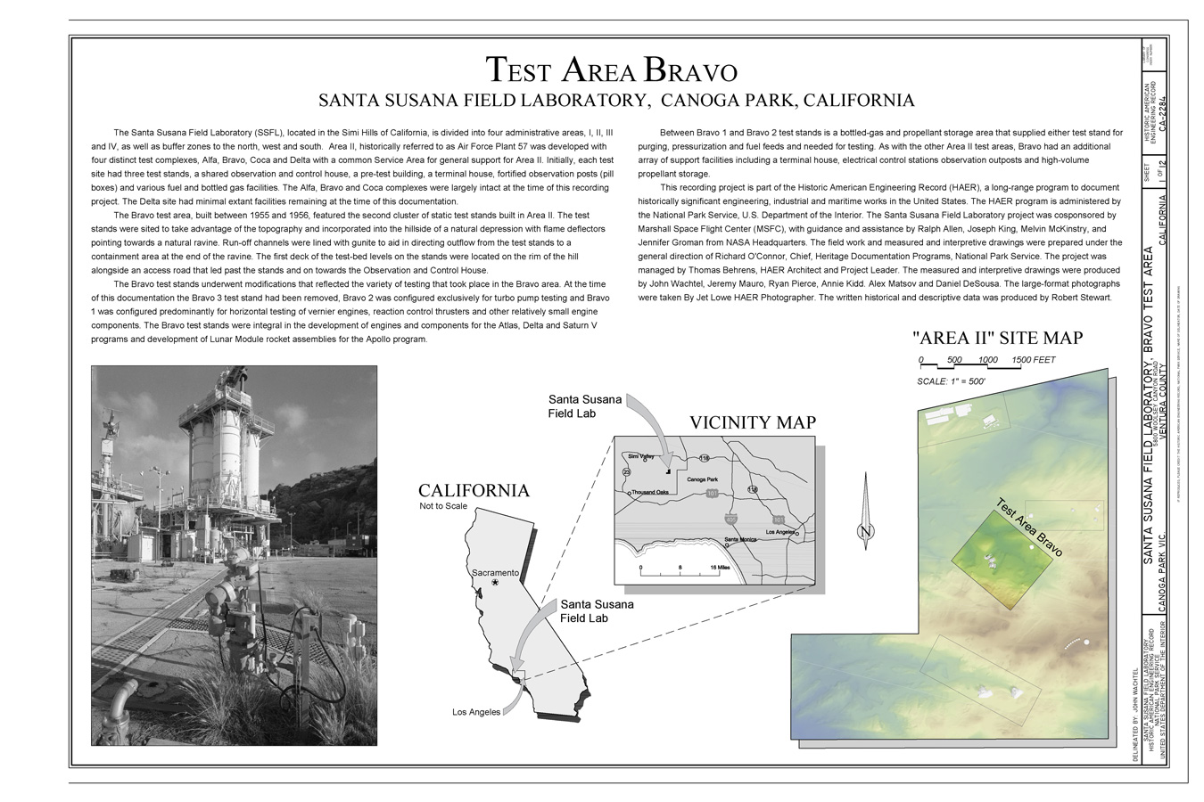
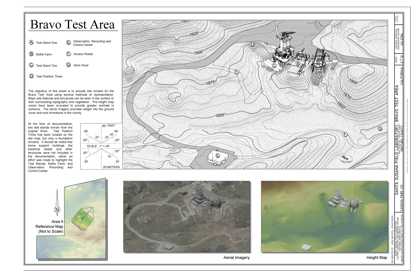
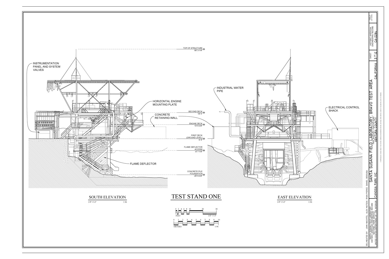
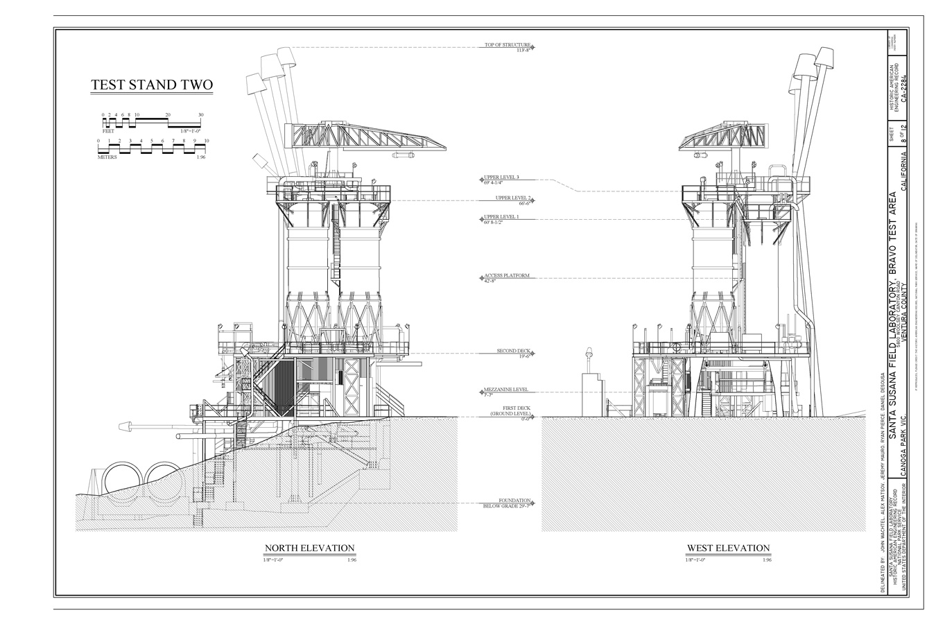
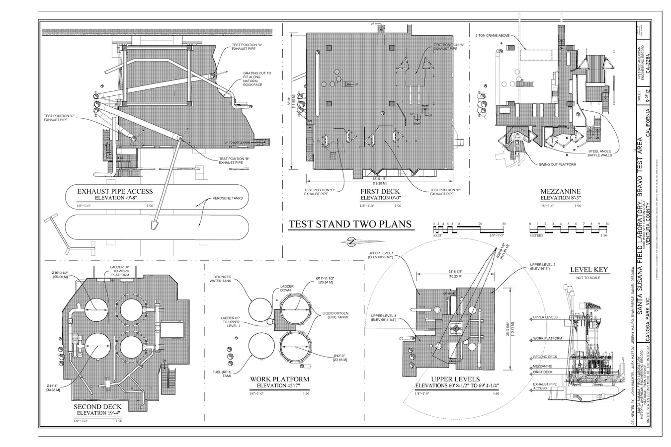
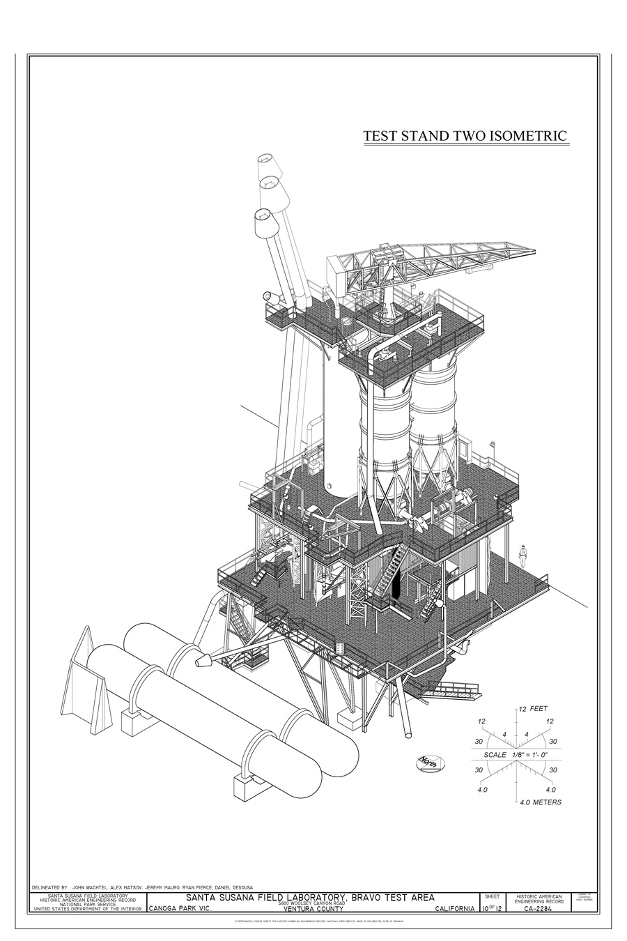
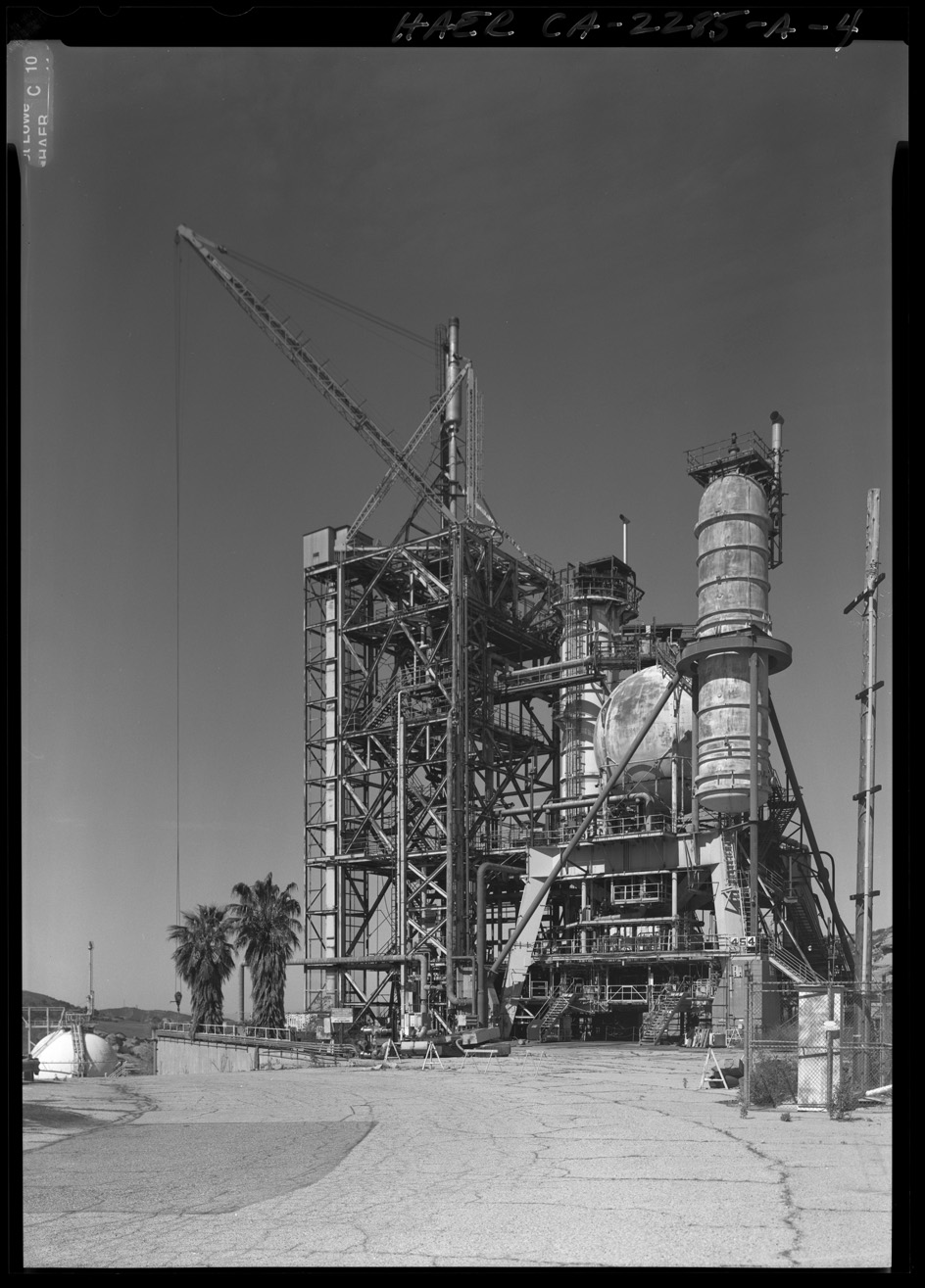
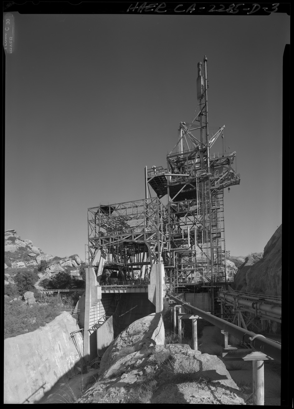
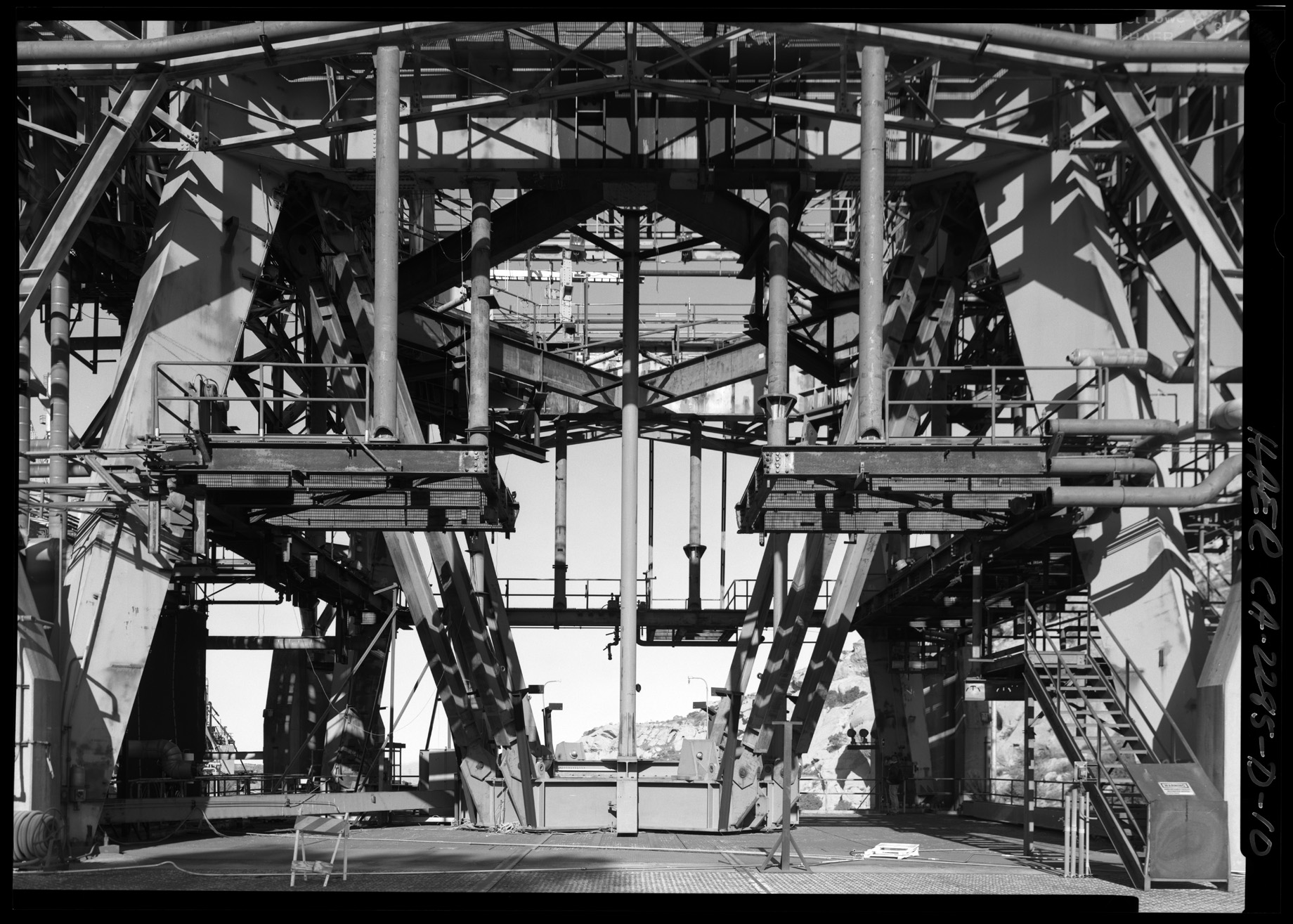
The Bravo test area, built between 1955 and 1956, featured the second cluster of static test stands built in Area II. The Bravo test stands underwent modifications that reflected the variety of testing that took place in the Bravo area. At the time of this documentation the Bravo 3 test stand had been removed, Bravo 2 was configured exclusively for turbo pump testing and Bravo 1 was configured predominantly for horizontal testing of vernier engines, reaction control thrusters and other relatively small engine components. The Bravo test stands were integral in the development of engines and components for the Atlas, Delta and Saturn V programs and development of Lunar Module rocket assemblies for the Apollo program.
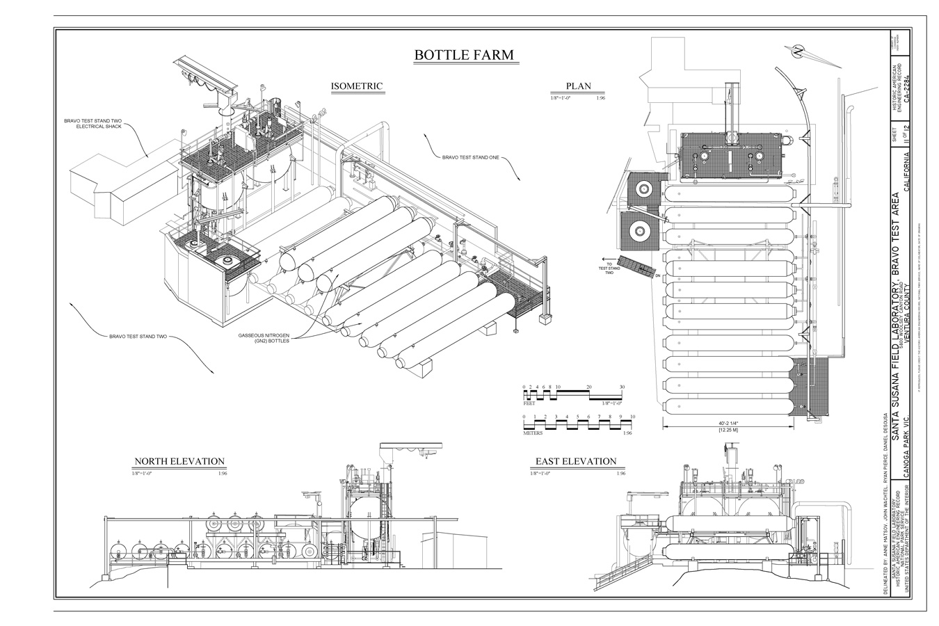
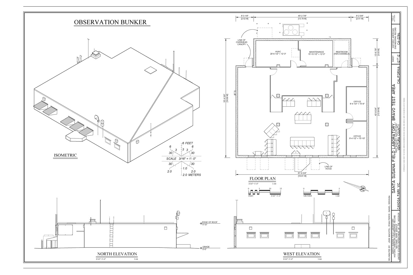
Between Bravo 1 and Bravo 2 test stands is a bottled-gas and propellant storage area that supplied either test stand for purging, pressurization and fuel feeds and needed for testing. As with the other Area II test areas, Bravo had an additional array of support facilities including a terminal house, electrical control stations observation outposts and high-volume propellant storage.

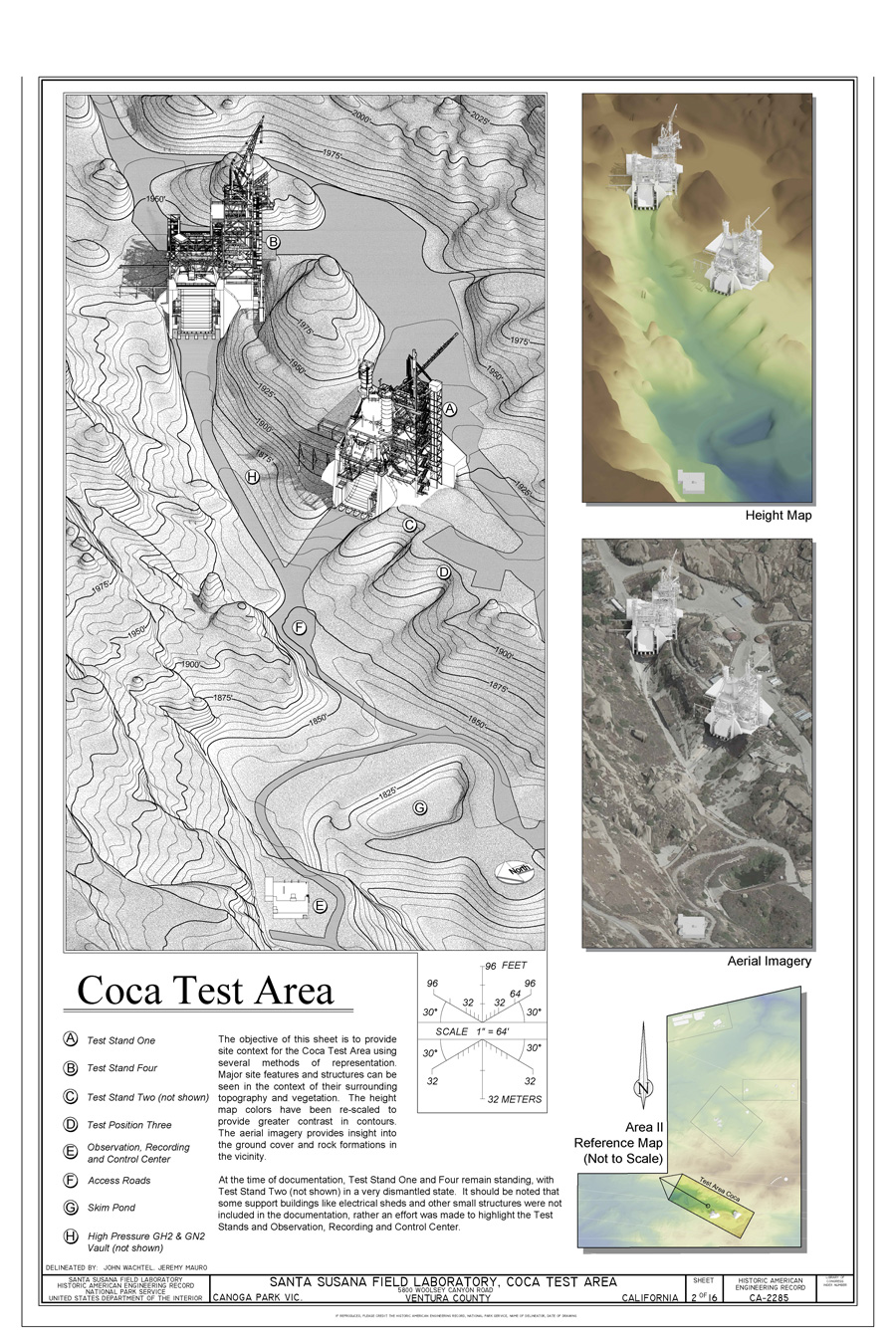
Coca Area
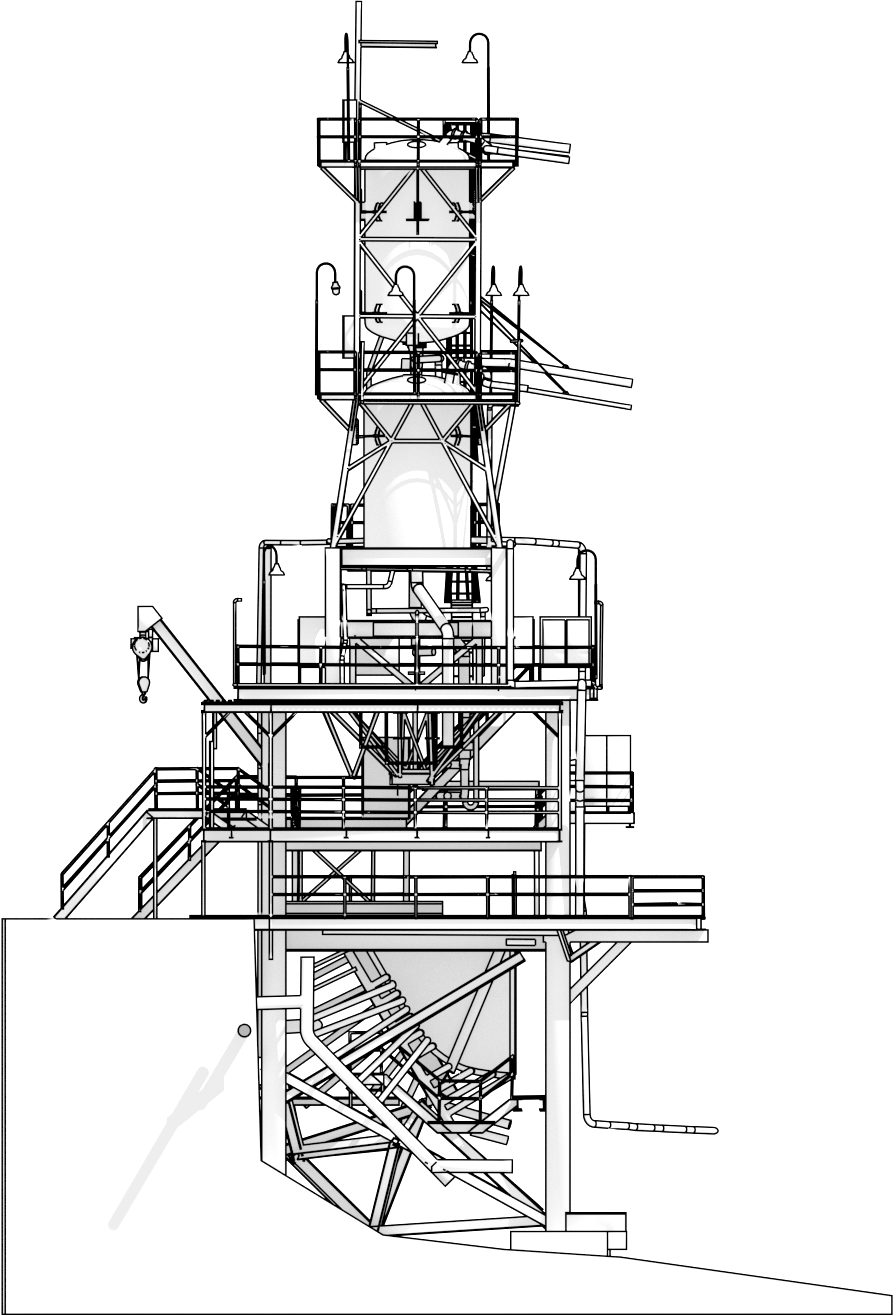
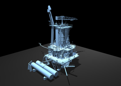
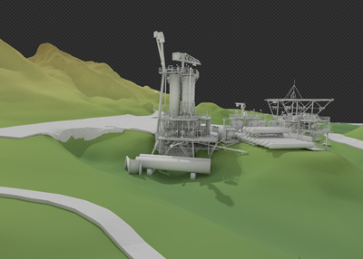
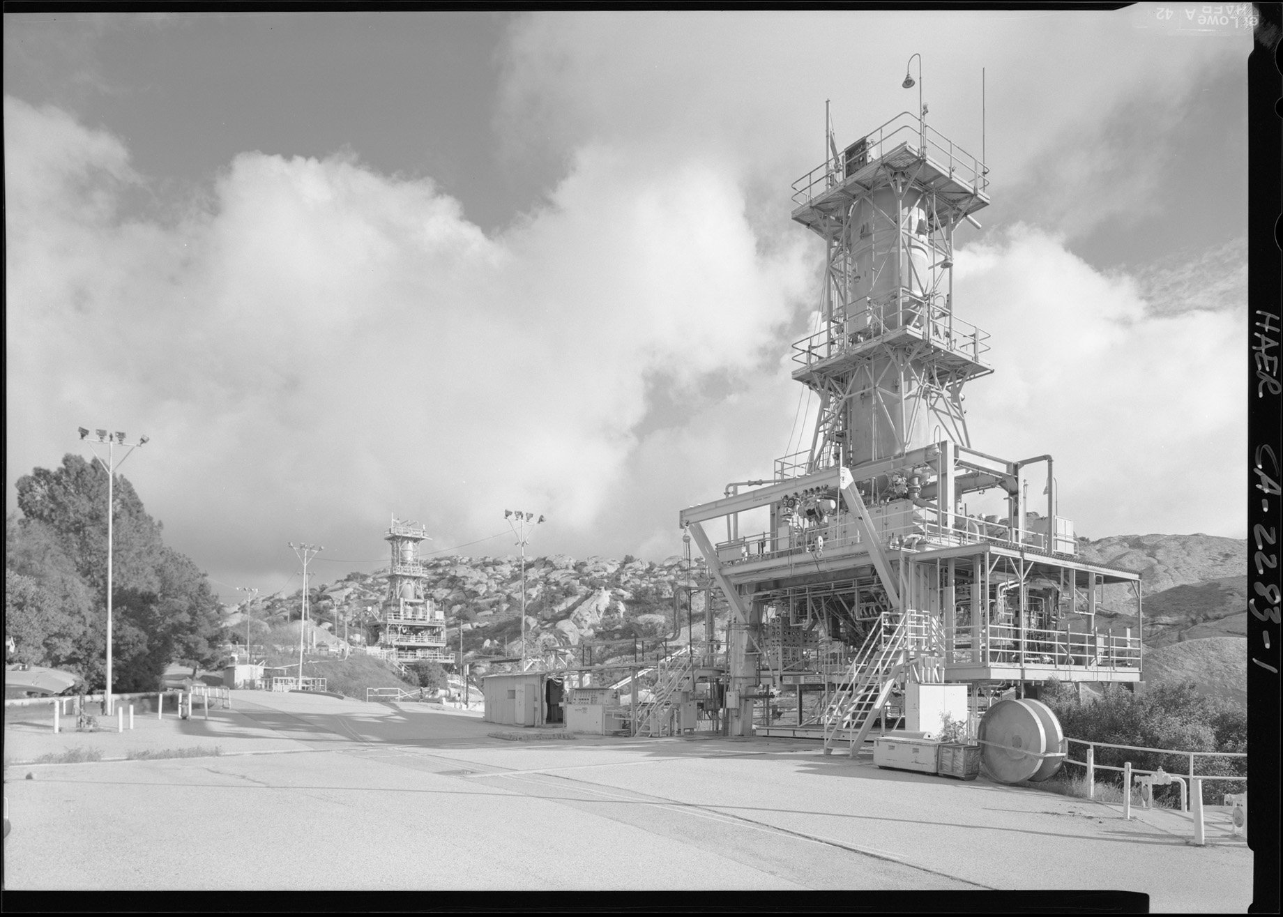
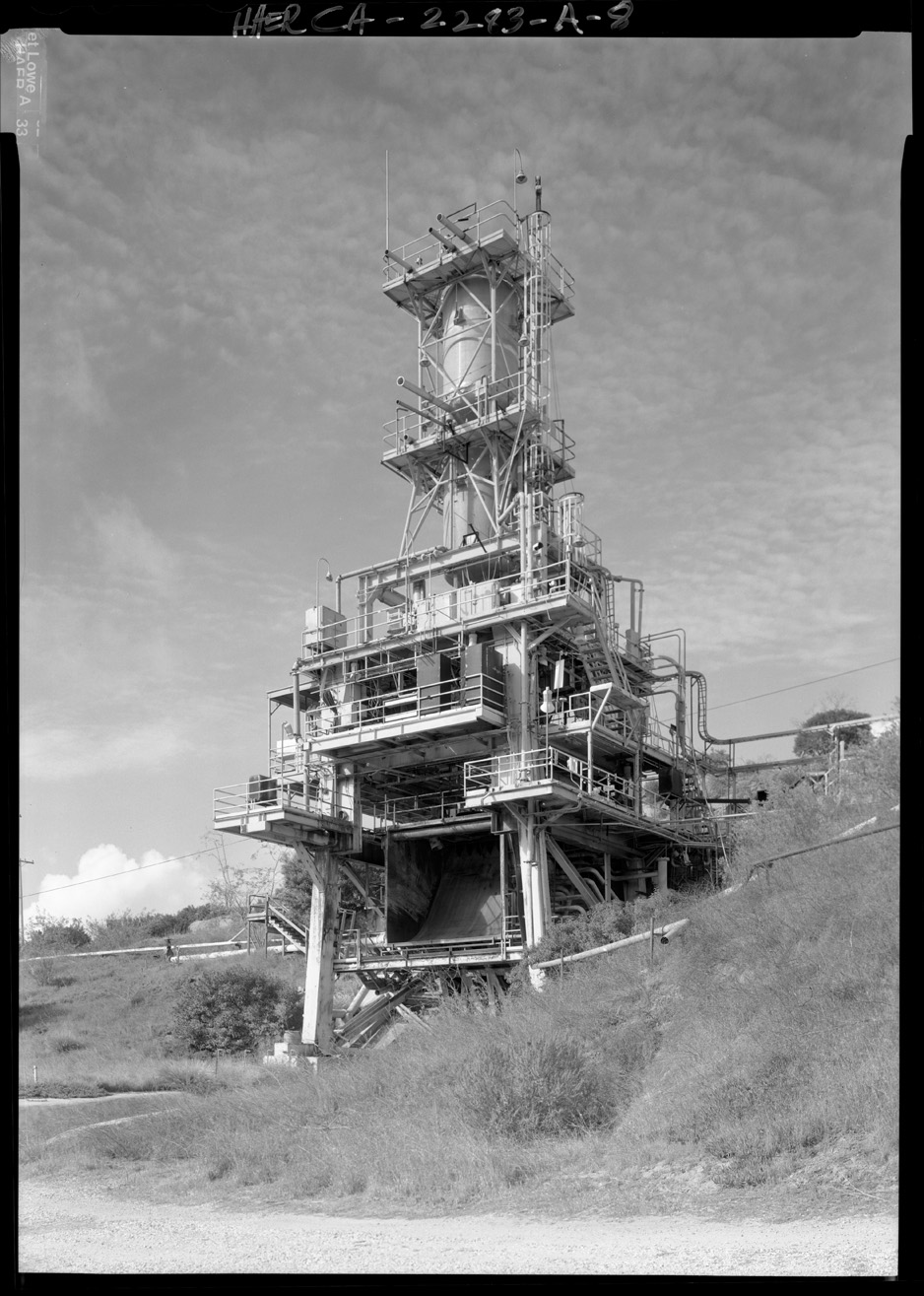
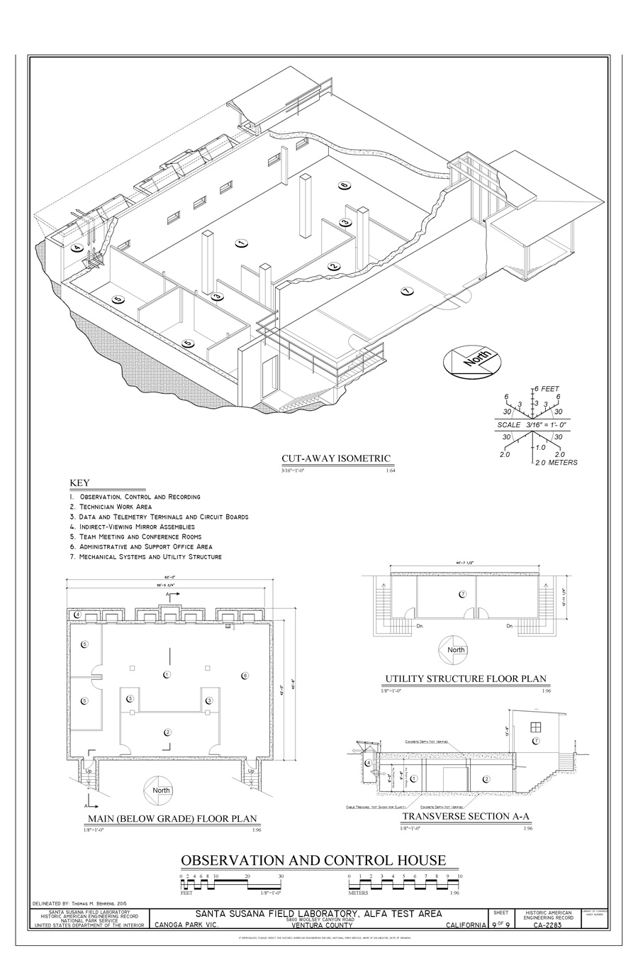
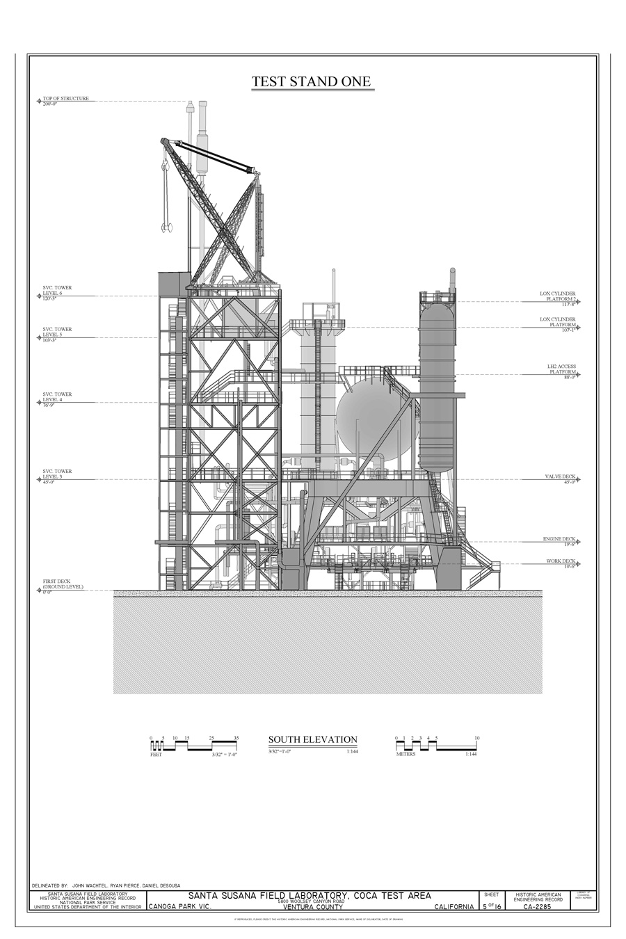
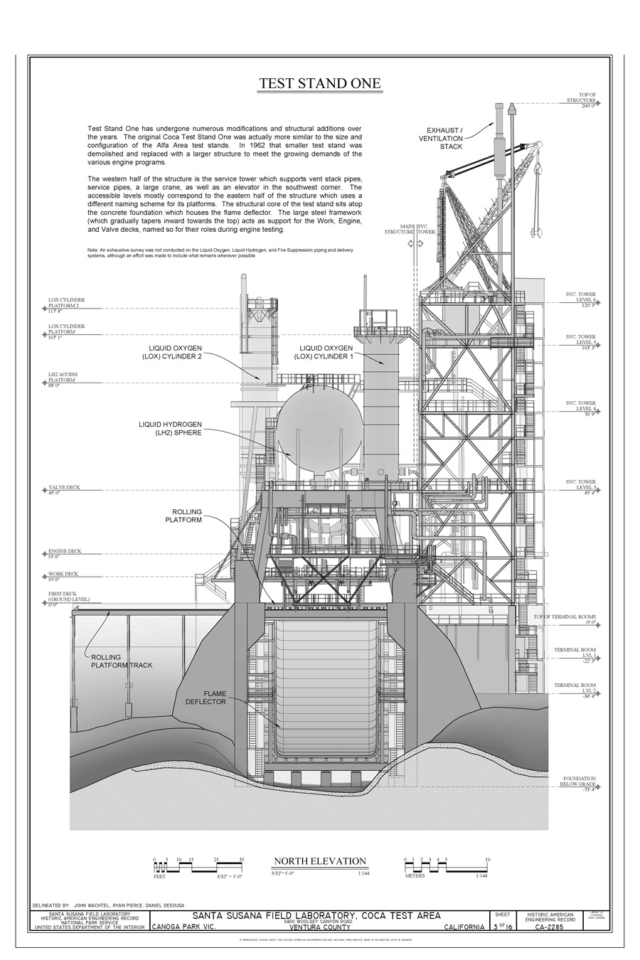
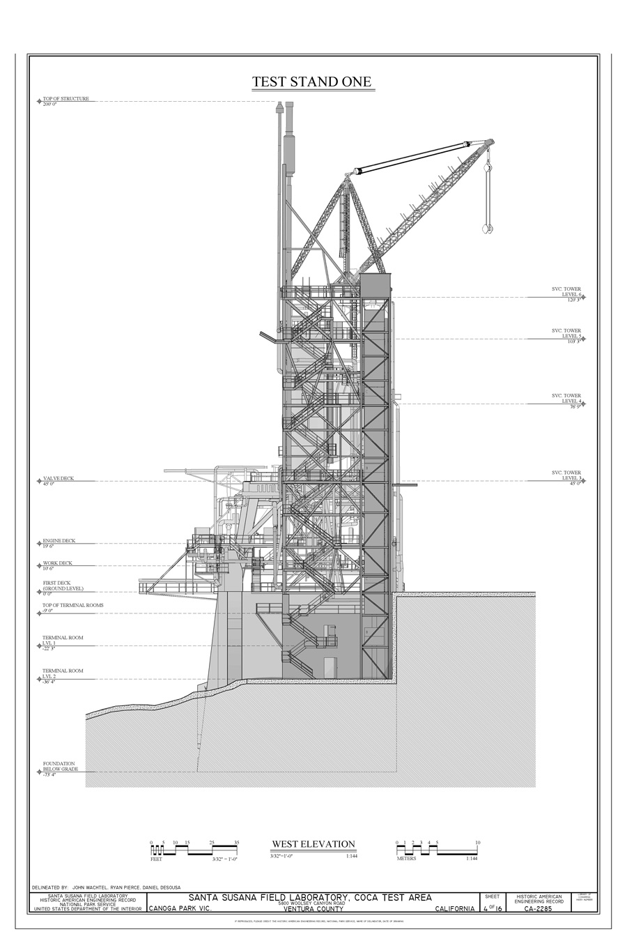
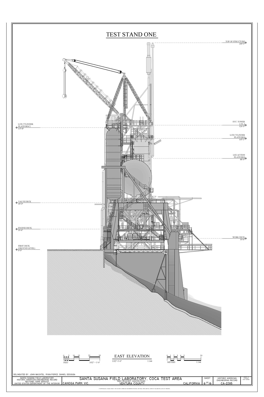
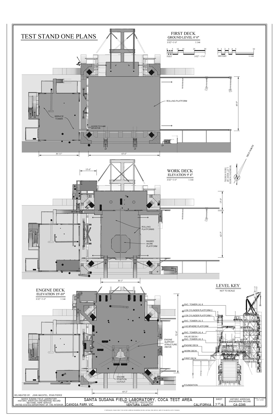
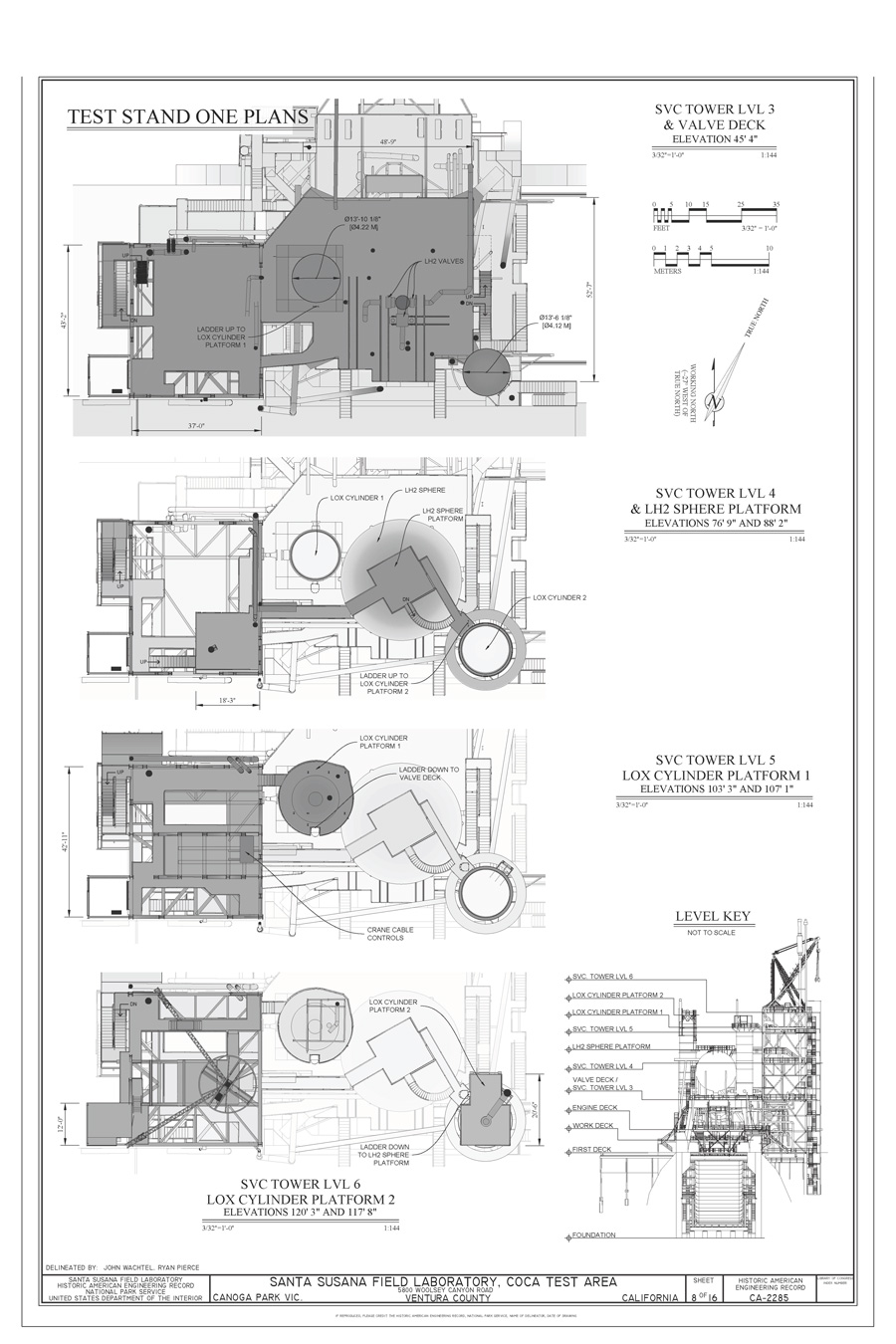
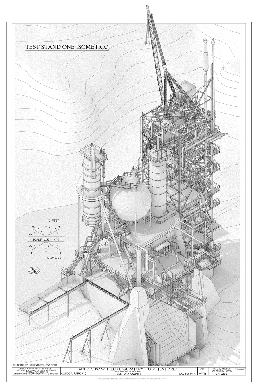
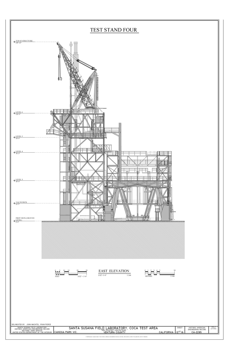
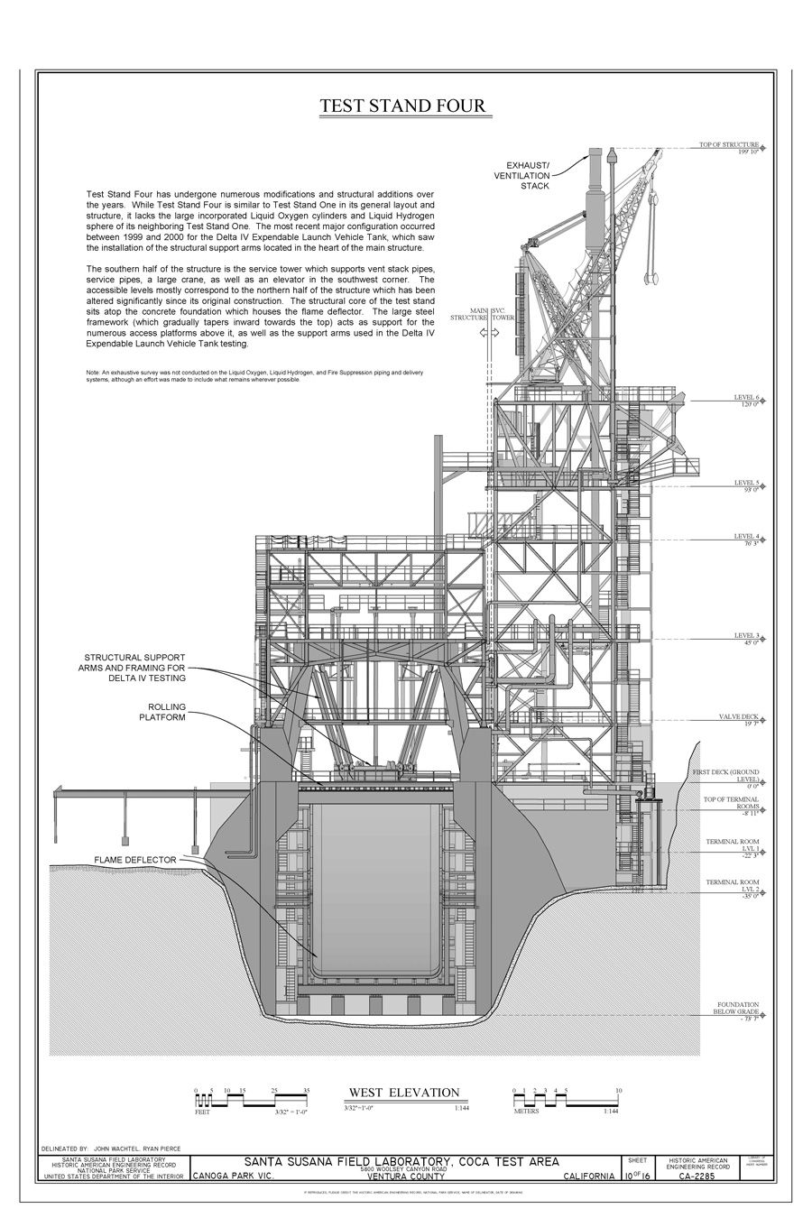
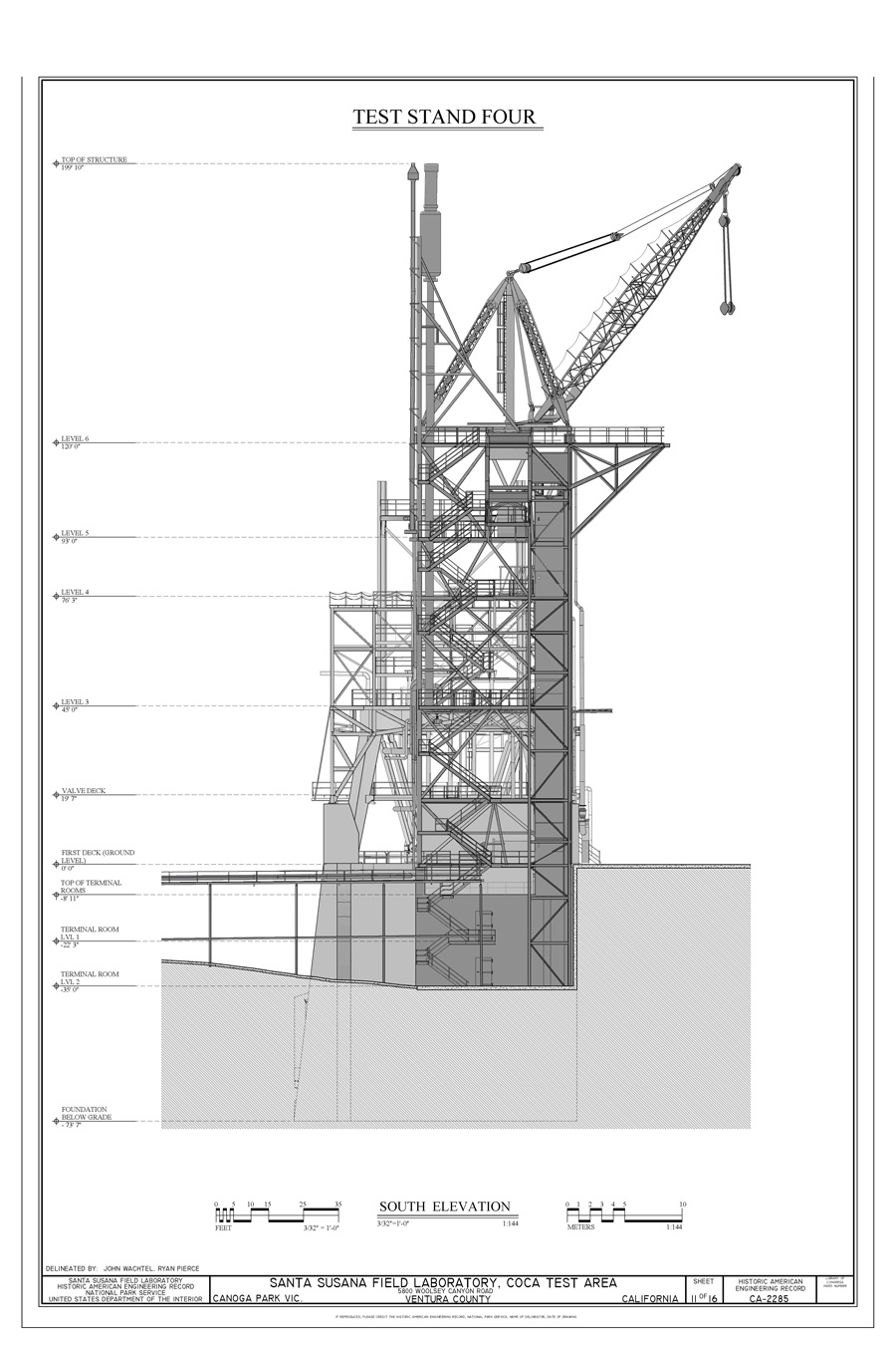
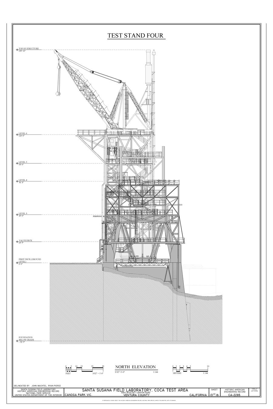
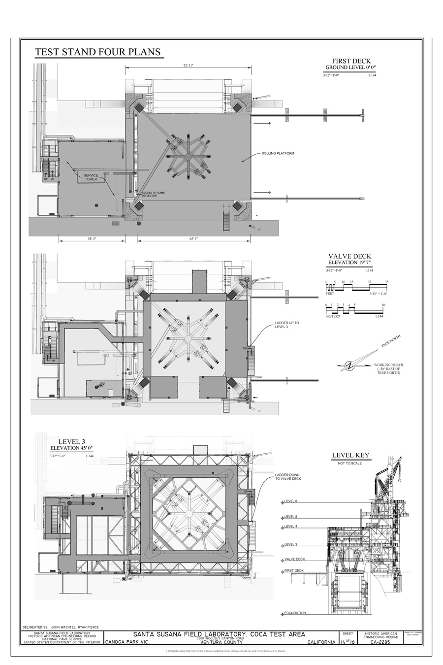
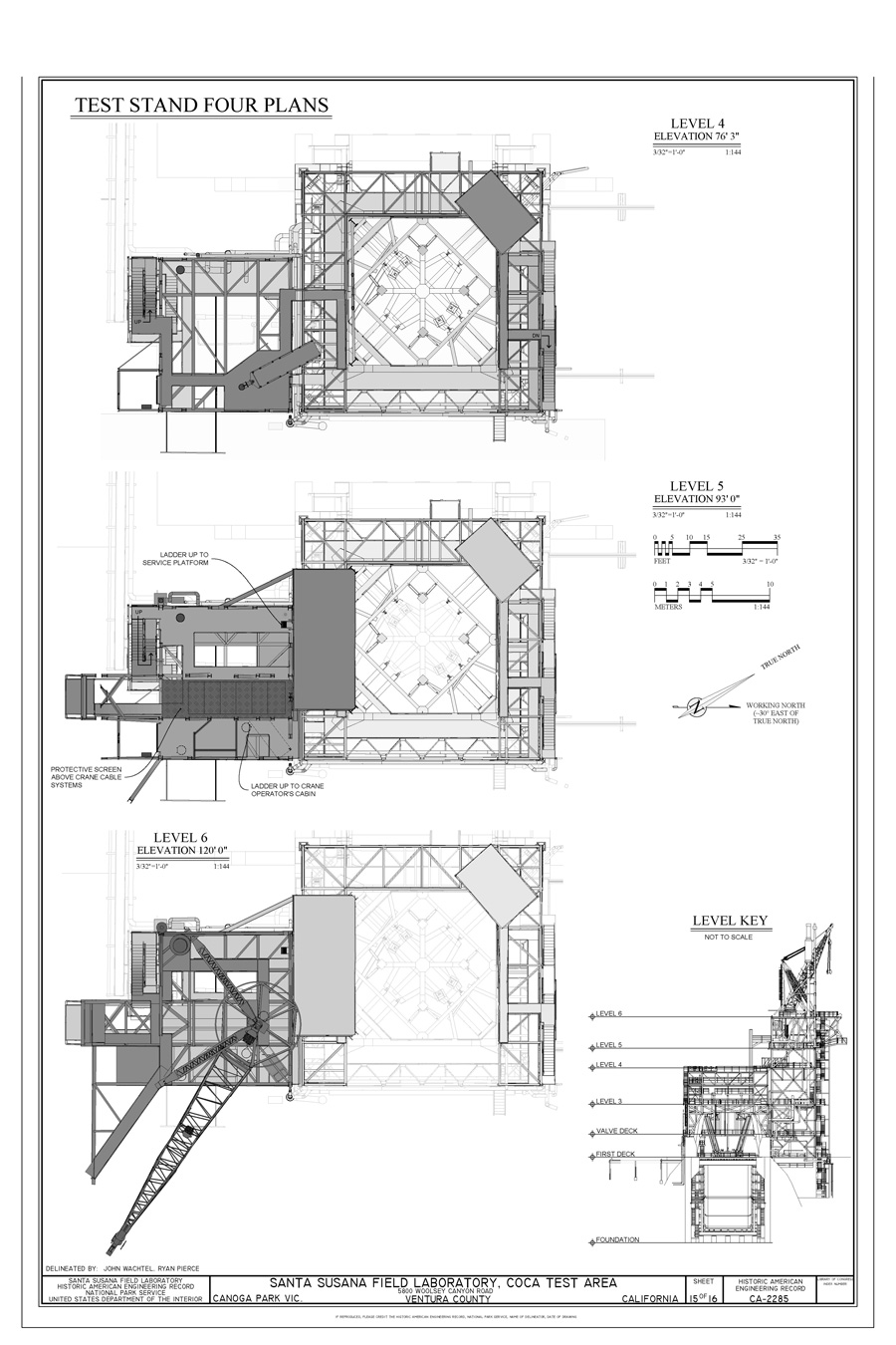
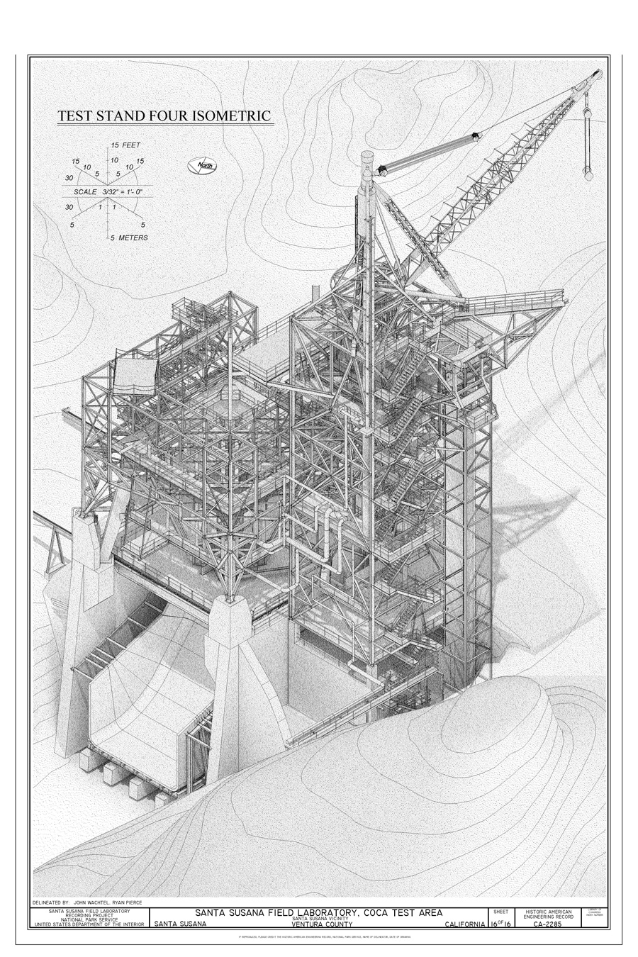
Of the extant test areas in Area II of the field laboratory, Coca was the most heavily modified from its original configuration. In the early 1960s Coca Test Stand One was disassembled and a newer, much larger facility was constructed on its site. This test stand was designed with a service tower structure and a test bed structure integrated as one facility. A second test stand with this configuration was erected at a new test position in the Coca area making it the fourth test stand in that area. Both of the test stands had independent terminal rooms located within the foundation of the service structure. A new cable tunnel was constructed that linked the Observation and Control House with the new test stands. The Observation and Control House was also enlarged to accommodate the new stands and the programs that would use these facilities.
The engines that were being tested on the enlarged test stand used liquid oxygen and liquid hydrogen as their propellant. As a result, facilities for the handling and storage of large quantities of hydrogen were constructed in close proximity to the east of the Coca test area and facilities for the storage and handling of liquid oxygen were located to the west of the test stands.
The Coca test area underwent its final modification in the 1970s in preparation for testing and acceptance of the Space Shuttle Main Engine design and construction. In conjunction with the Mississippi Test Facility (now Stennis) the Coca test area developed the initial Space Shuttle engines.
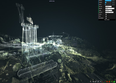
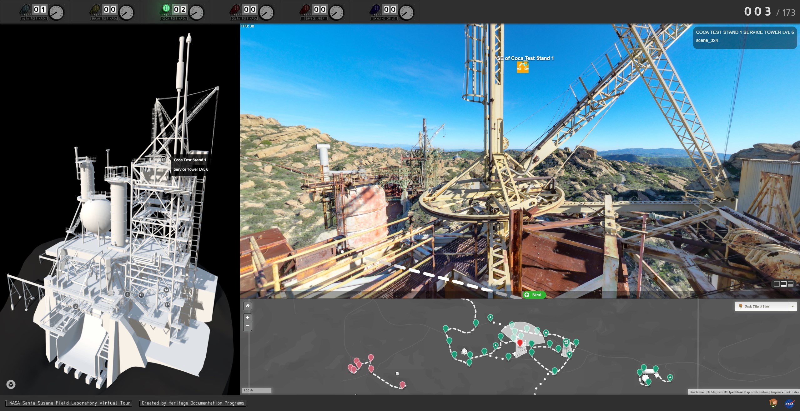
Want to take a virtual tour?
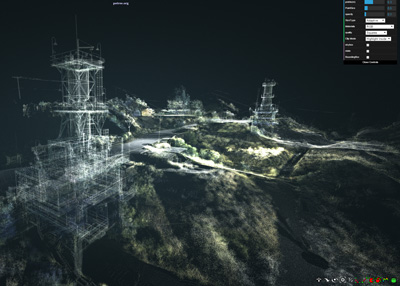
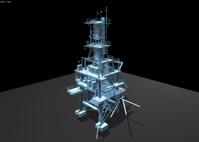
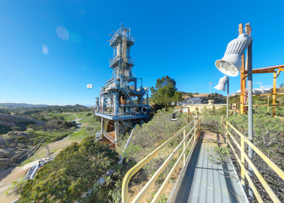
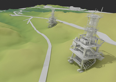
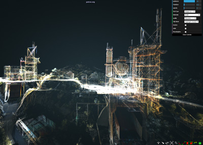
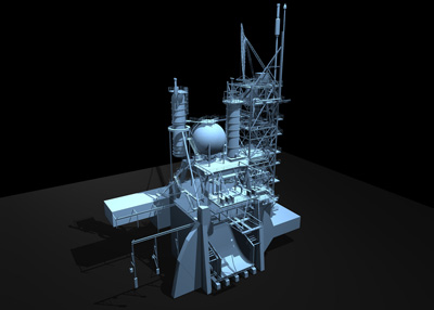
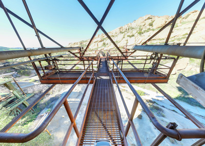
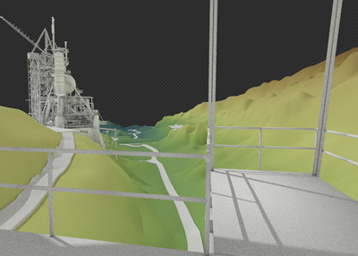
To further explore the test stands and various sites at Santa Susana, be sure to visit the virtual tour. The interactive virtual tour presents the drawings, photographs, 3d models, videos and point clouds in the context of the landscape using panoramic photography.
Click the link below to begin taking the tour now!
Heritage Documentation Programs

NASA Santa Susana Field Laboratory