Preserving our nation's historic buildings
Technical Preservation Services develops historic preservation standards and guidance on preserving and rehabilitating historic buildings, administers the Federal Historic Preservation Tax Incentives program for rehabilitating historic buildings, and sets the Secretary of the Interior's Standards for the Treatment of Historic Properties.
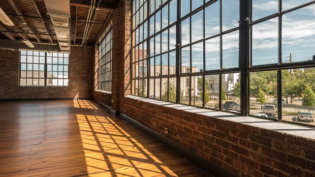
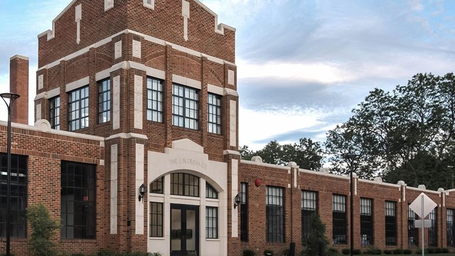
Banner photo: The Bottleworks, Indianapolis, Indiana, Susan Fleck; Courtesy RATIO Design and Hendricks Commericial Properties